Miscellaneous CAD
Overview
Here are some of my favorite CAD models I’ve made. Details of my 3D modeling processes are below.
Modeling a Car: Lamborghini Aventador
I’ve always wondered how cars are 3D modeled – the complex and curvilinear surfaces were a mystery to me. During Summer 2021, I decided to finally jump in and learn how to CAD a car.
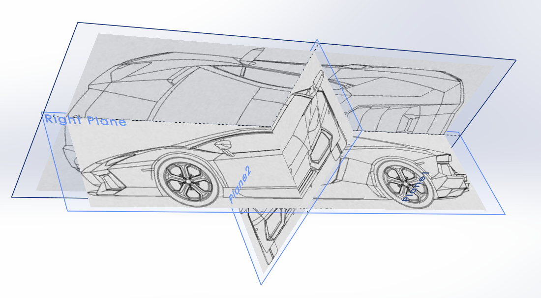
I began by finding blueprints of the top, side, front, and back views of the Lamborghini Aventador.
I then laid them out on planes.
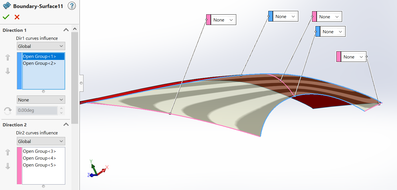
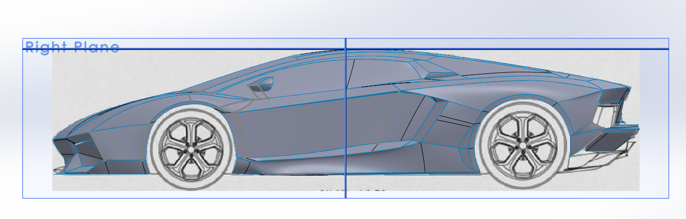
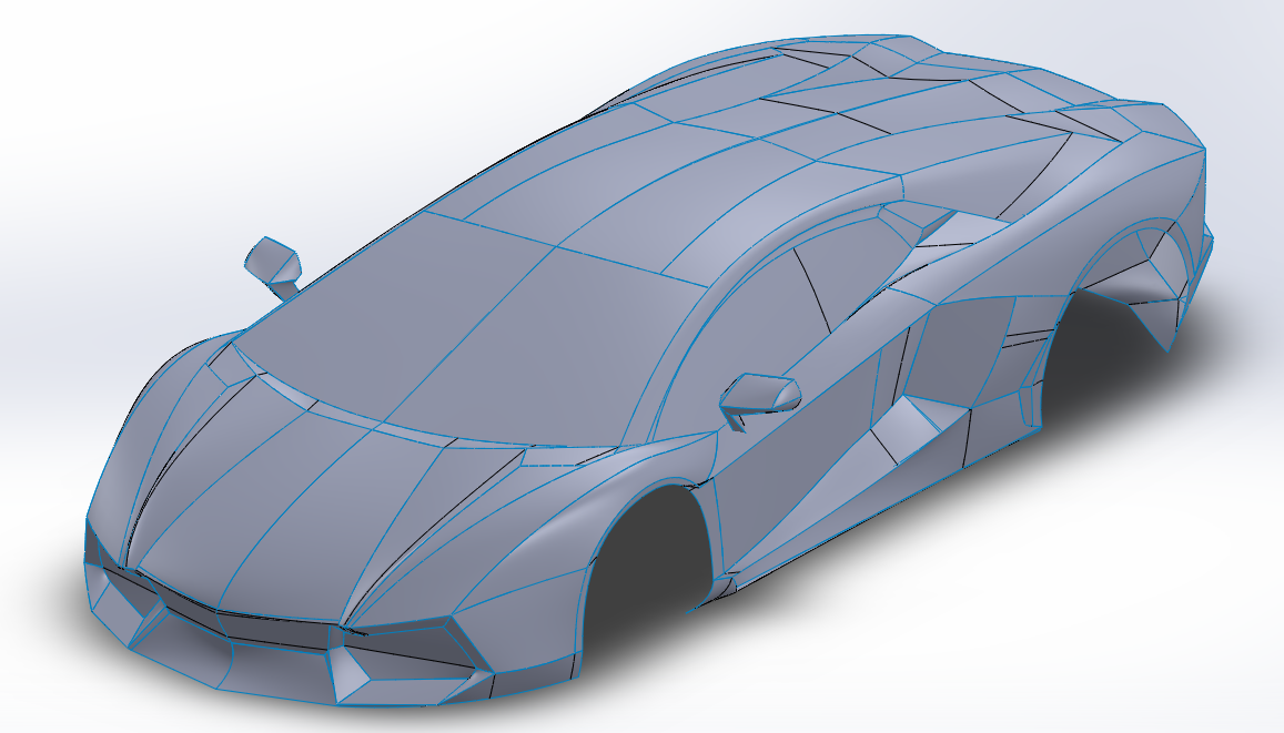
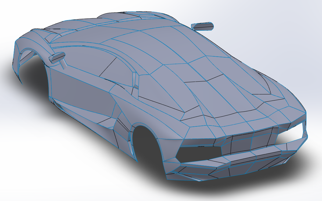
After that, I started making boundary surfaces to model the shapes of each face, constantly switching between the front, back, side, and top views to match the edges of my surfaces to the blueprints.
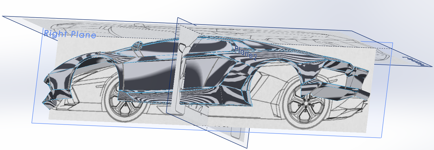
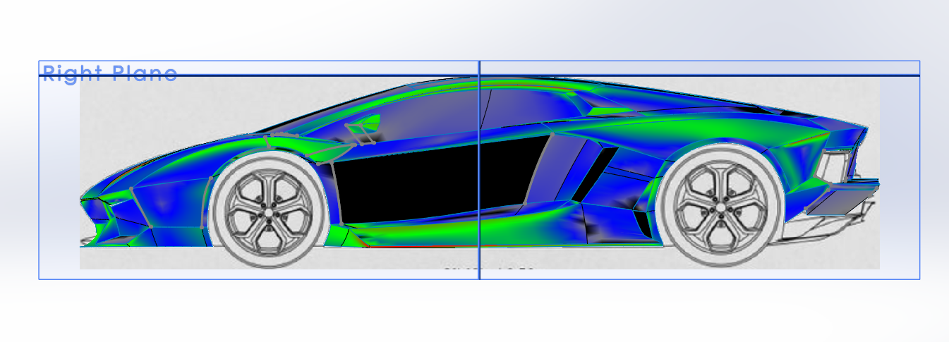
Using SolidWorks Evaluate tools such as Zebra Stripes and Curvature helps to confirm that the boundary surfaces have the correct curvature and edges.
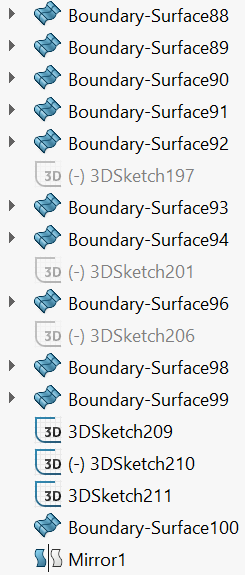
By the end, I had exactly 100 boundary surfaces and over 200 sketches (each boundary surface is made up of 2-3 sketches).
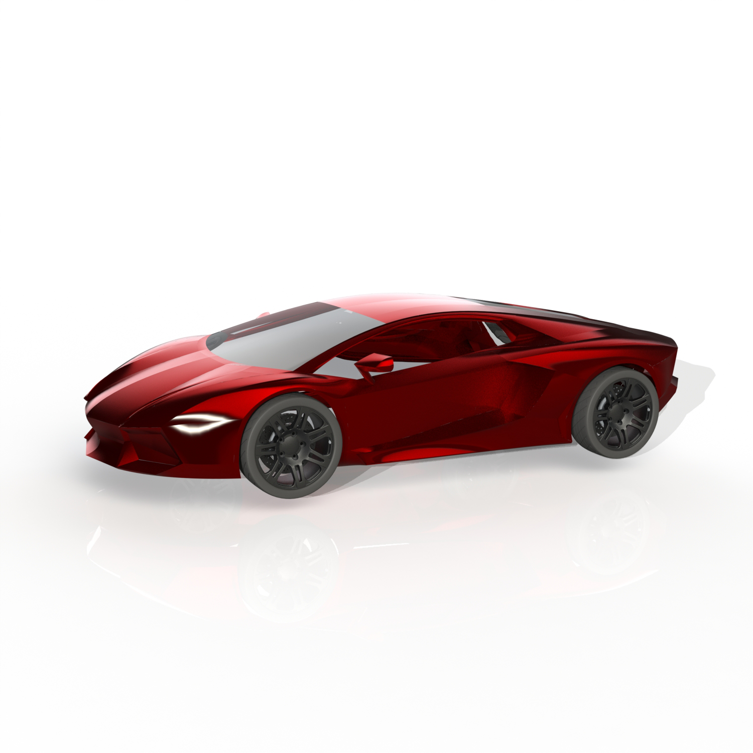
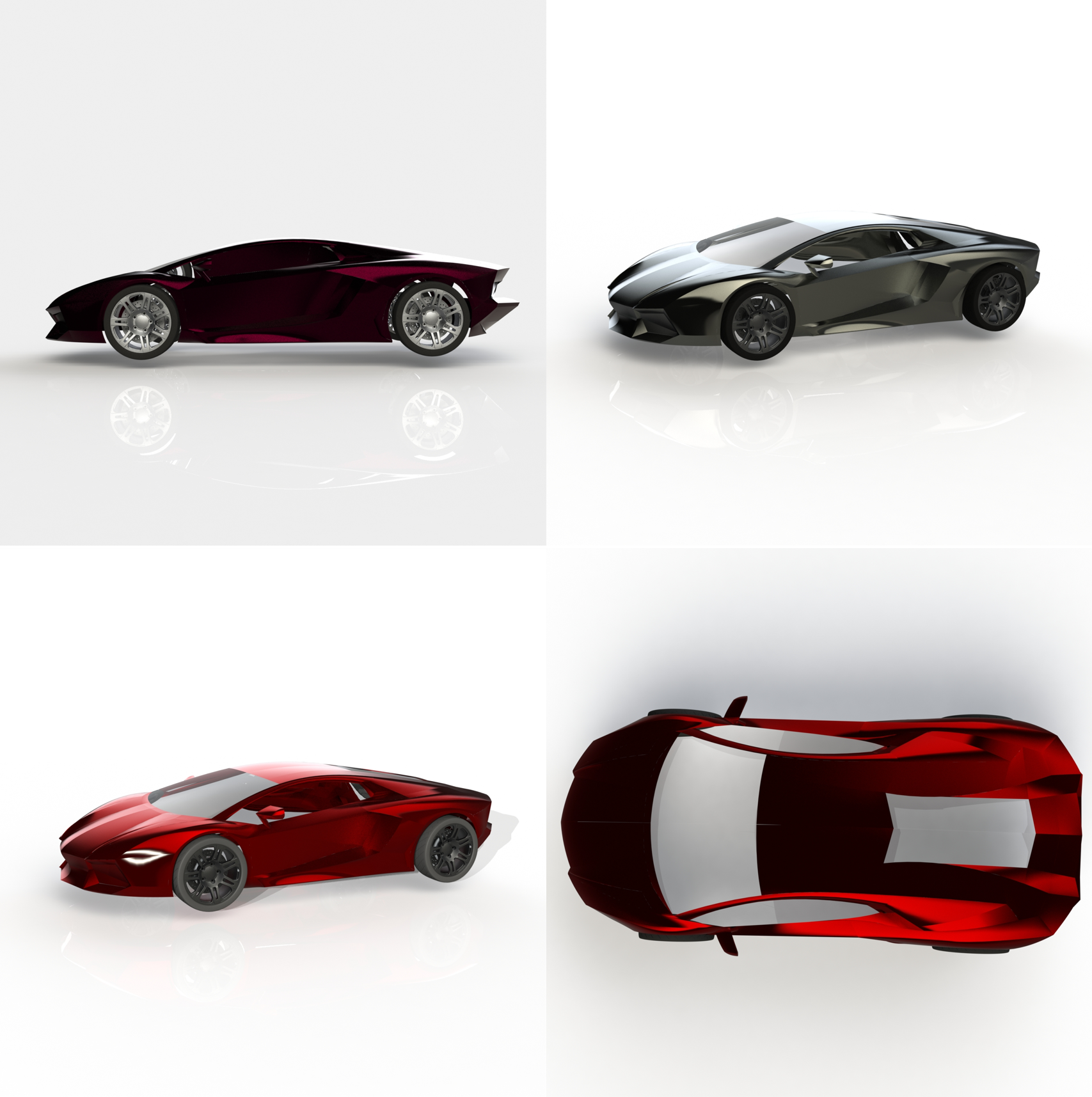
When I finished all the surfaces, I then used the PhotoView 360 SolidWorks add-in to render my car. Here are the final renders!
Modeling a Building: Barcelona Pavilion
For my HIAA0850 final project, I constructed a digital 3D model of the Barcelona Pavilion (arch. Ludwig Mies van der Rohe). My process involved creating the 3D CAD model of the Barcelona Pavilion in SolidWorks, assigning materials and setting up lighting, scenes, and camera positions in Adobe Dimension, producing photo-realistic renders in Adobe Dimension, editing rendered photos in Adobe Lightroom, and putting together flythrough clips and edited renders in Adobe Premiere Pro, producing a final video.
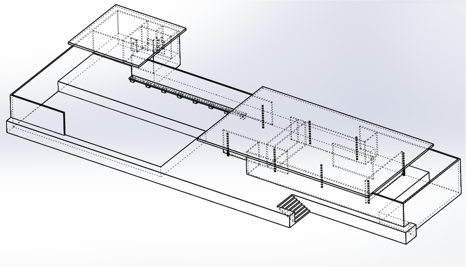
In creating the CAD model, I overlaid the floor plan and front, side, and back views of the Pavilion onto the Front, Top, and Right planes in SolidWorks. I began tracing 2D projections over the blueprint. Then, I extruded these 2D sketches, resulting in 3D walls. I added in details afterwards, such as the sunken area for the pools of water, the panels of glass, and the structural supports.

For the renders, I assigned materials to the walls of my CAD model. Adobe Dimension’s material selection is limited, so occasionally I needed to substitute in visually similar materials, such as using cedar wood for the marble floors and ceilings. I also needed to adjust the materials’ roughness, pattern repetitiveness, reflectivity, and color.
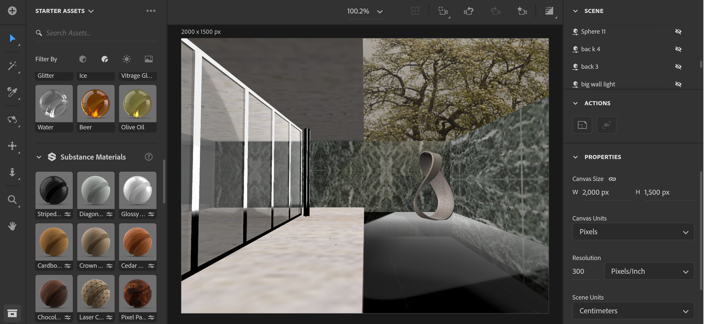
I also needed to set the lighting in my scenes; I experienced the difficulty of interior lighting. I learned how to strategically place lights to illuminate the greatest area with walls as constraints. A similar computational geometry problem, the art gallery problem, is a problem of guarding an art gallery with the minimum number of guards who together can observe the entire gallery, which has walls and concave side rooms. The trick is to place the guards at the vertices of the side rooms so that they can see into the side rooms as well as portions of the main room. Following this principle, I placed my lights at the vertices of the Pavilion’s side rooms when I needed to illuminate the building interior.
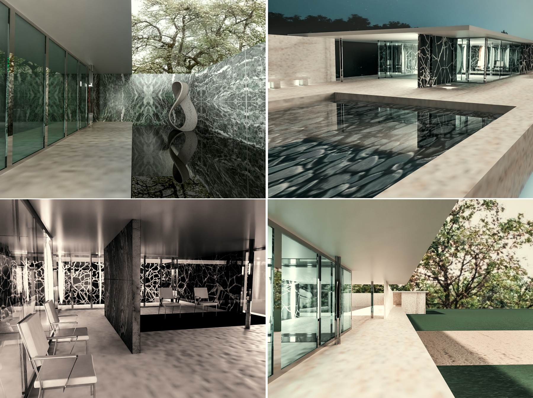
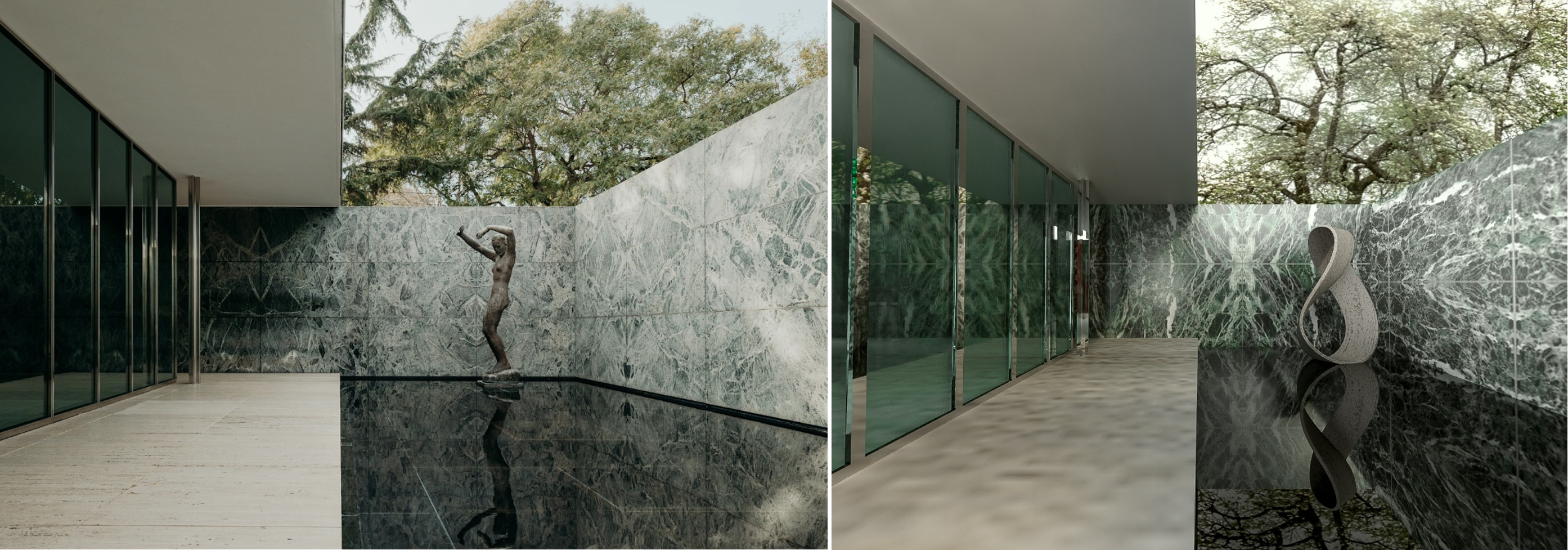
Here’s a comparison of the real-life photo vs. my rendered CAD model!
ENGN1740: Computer Aided Visualization and Design Projects
In my ENGN1740: Computer Aided Visualization and Design class at Brown University, our projects asked us to choose objects of varying complexity to model in SolidWorks and dimension in drawings that adhere to ASME Y14.5 2009 standards.
I decided to model the following objects:
-
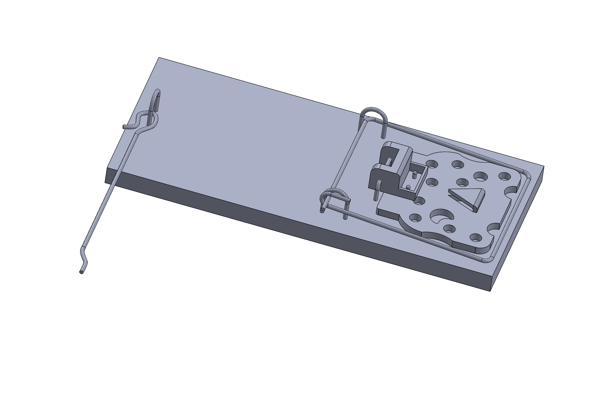
Mousetrap (assembly)
-
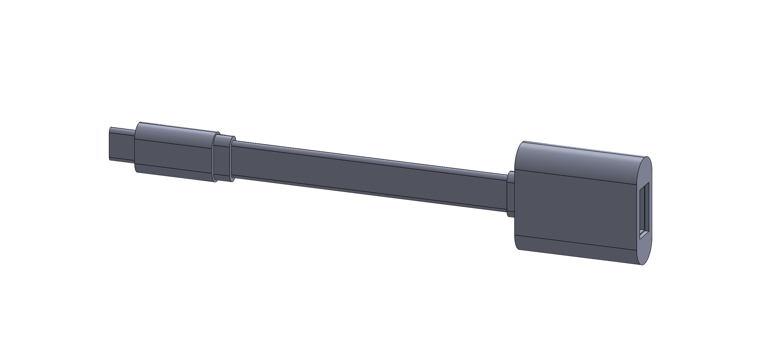
USB-C Adapter (part)
-
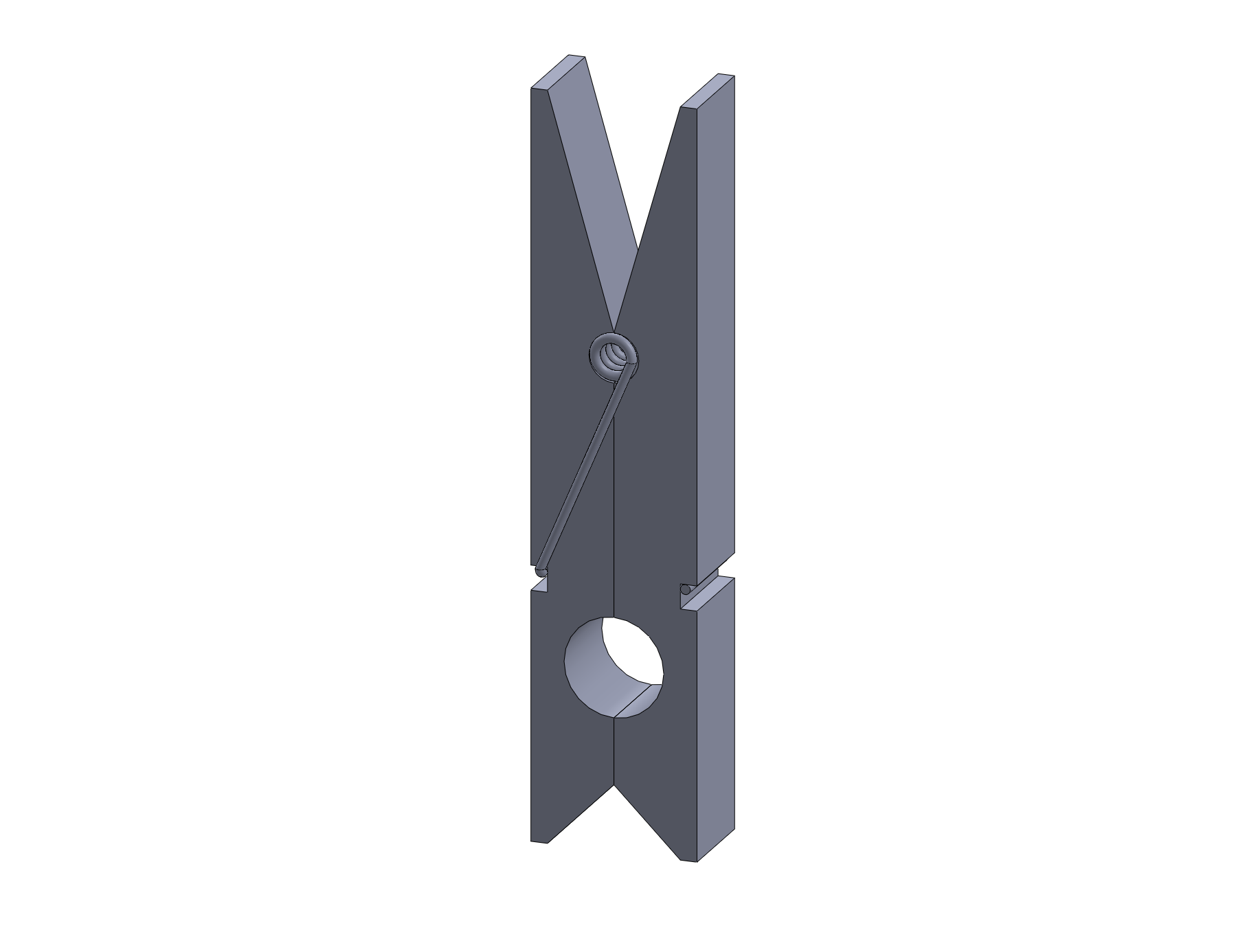
Clothespin (part)
-
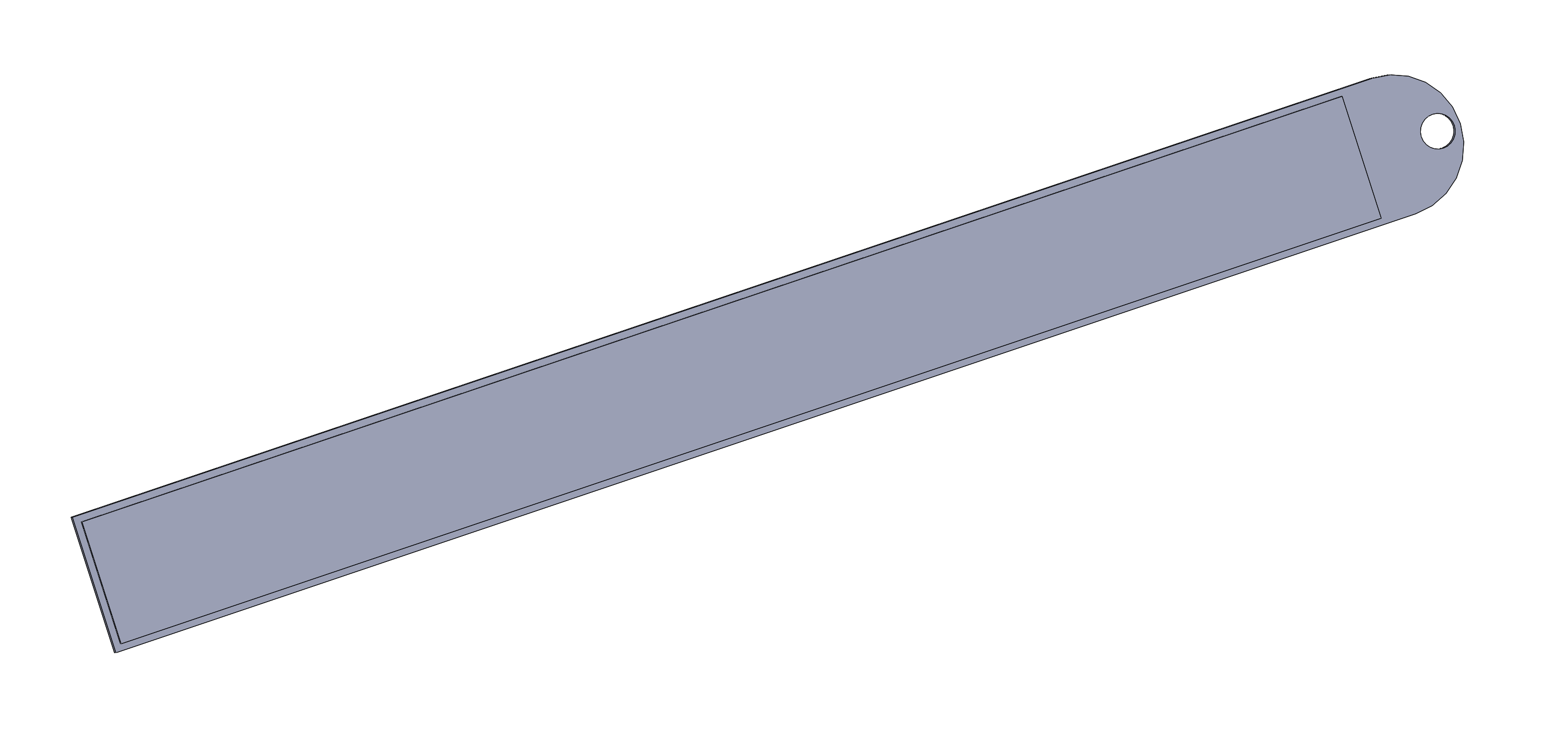
Ruler (part)
SolidWorks Models
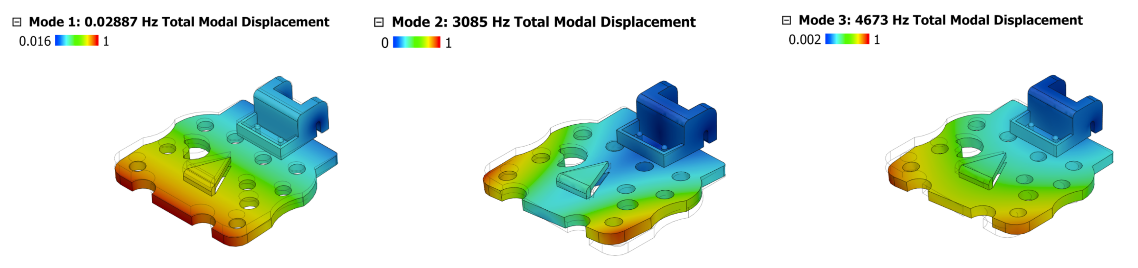
Modal Analysis
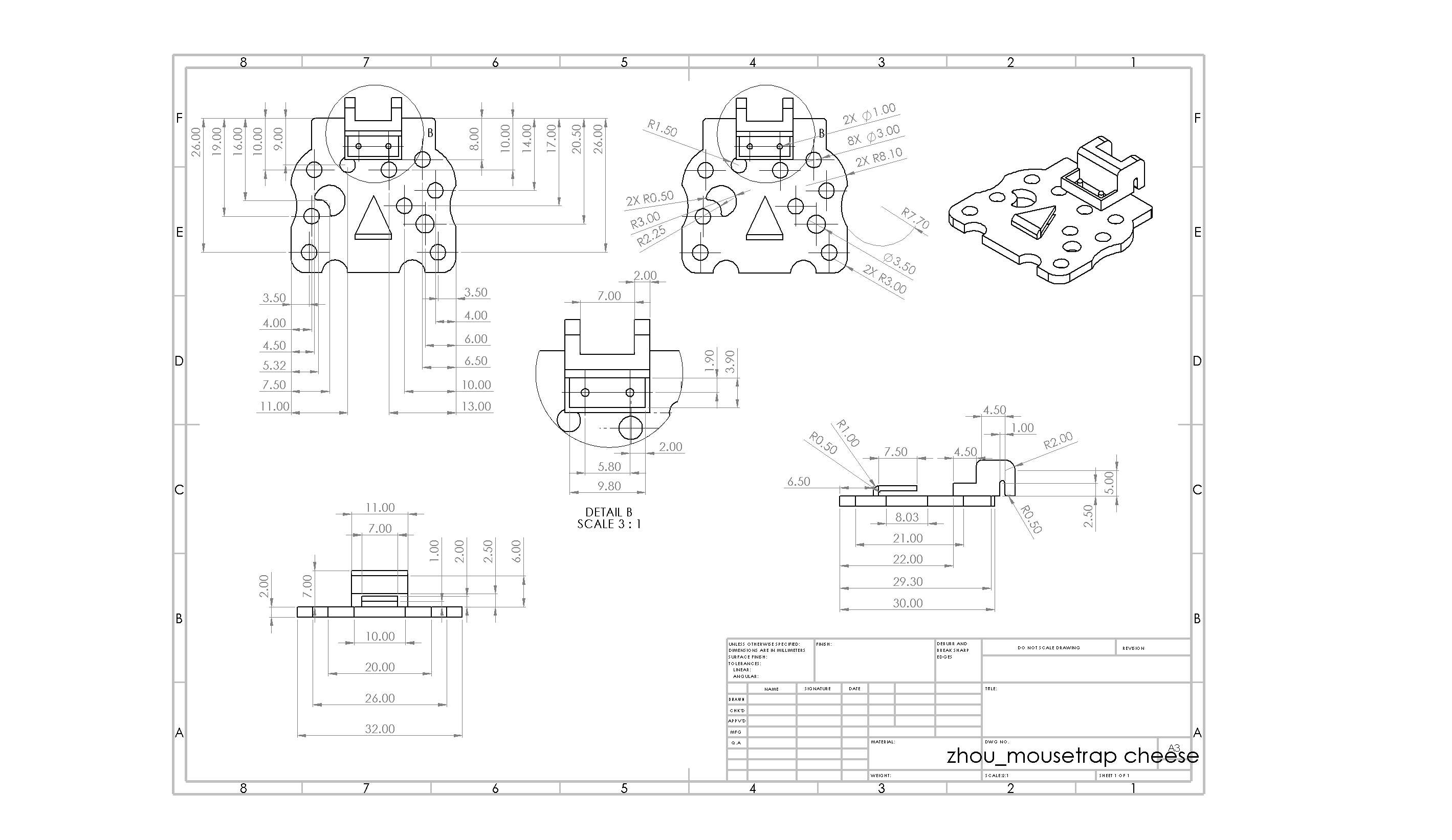
I performed modal analysis of the plastic cheese mousetrap component in Fusion 360. There are pin constraints in the connector area, a downward force from the bait on the triangular platform, and a point load from the trigger wire.
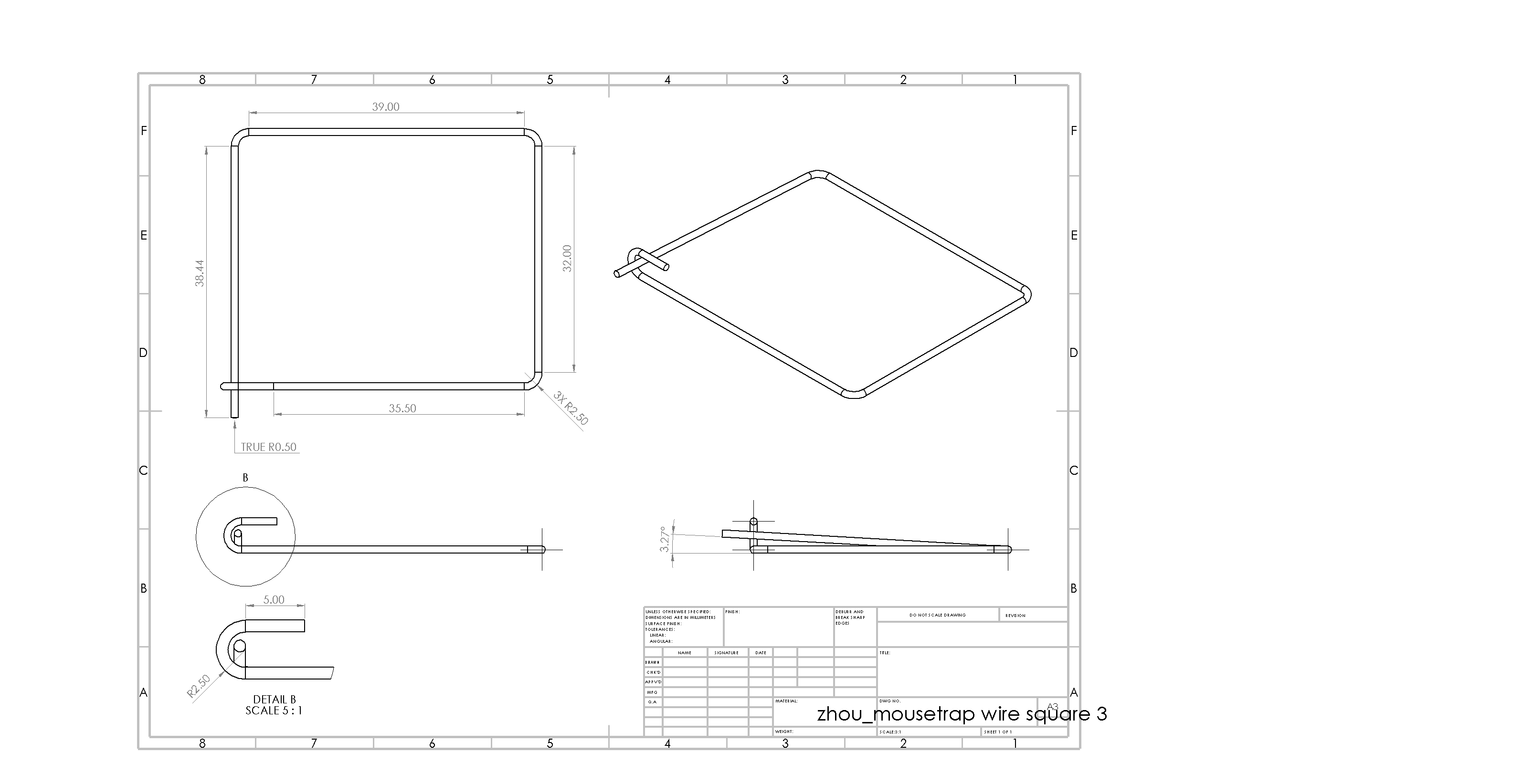
SolidWorks Drawings
For the mousetrap assembly, I made drawings of several mousetrap part components following ASME Y14.5 2009 standards.
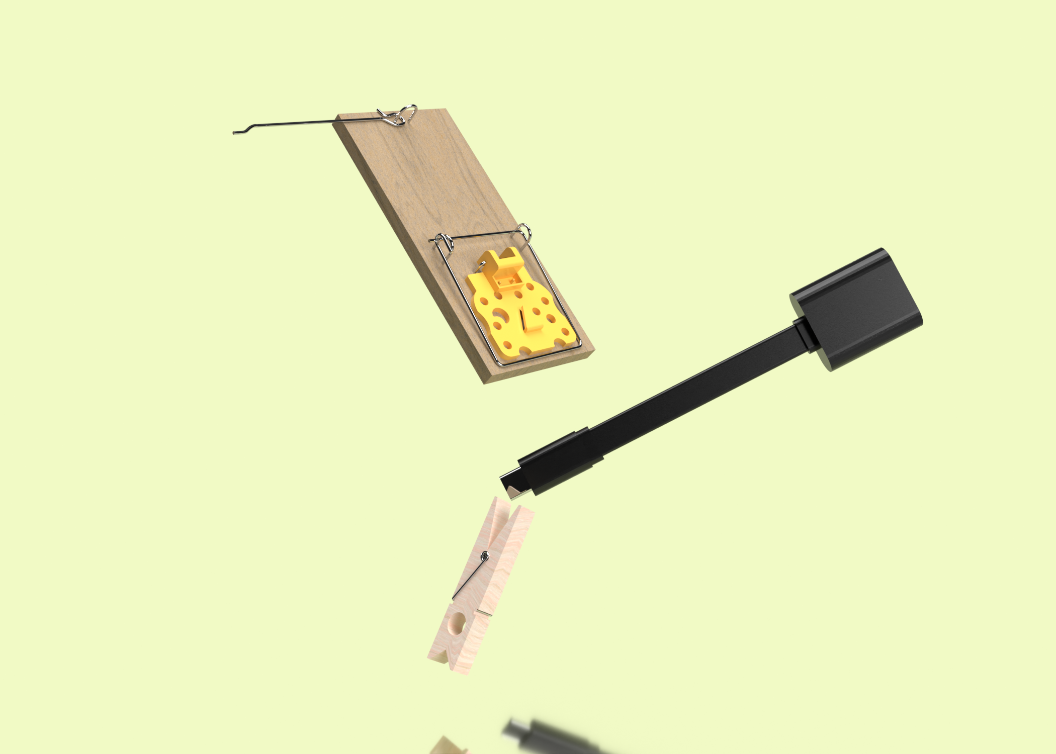
Final Render
I rendered a couple of the CAD projects in Adobe Dimension, for fun!
