Drop Tower
In Fall 2022, my team (Kevin LoGiudice, Venkatsai Bellala, Zabari Ross, and I) built a drop tower to impact biological samples, ranging from soft tissue to bone, in a sterile environment by varying weights and drop heights to control the applied force so the sample is damaged but not fractured.
Process
-
Brainstorm design concepts
-
Decision matrix
-
CAD
-
Design electronics
-
FEA
-
Assembly and refinement
-
Arduino
Brainstorm
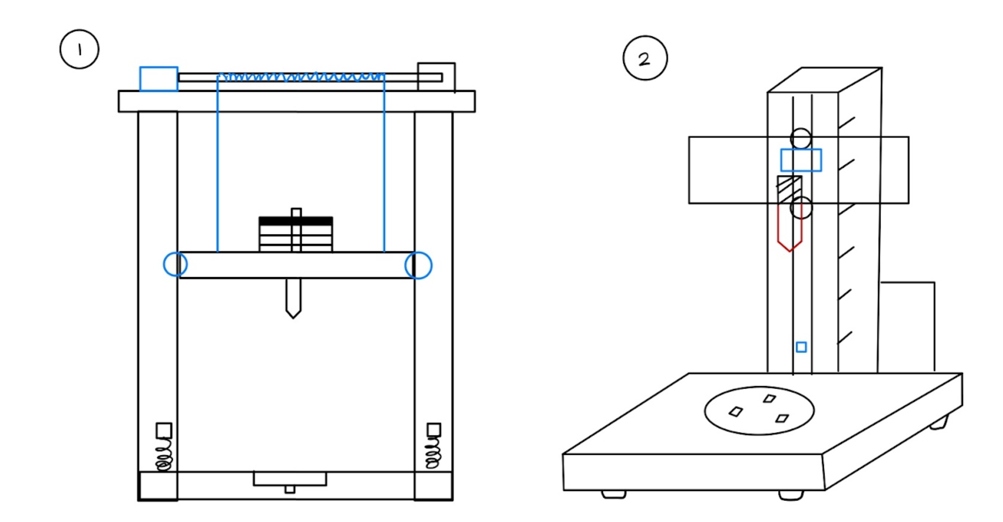
We began by brainstorming potential forms for our drop tower. Classic drop towers (e.g. Instron Dynatup 9400 Series) typically feature an impactor attached to a platform that slides on two rails. Basing our concepts off existing products, we came up with 4 options. 2 are depicted below.
Decision Matrix
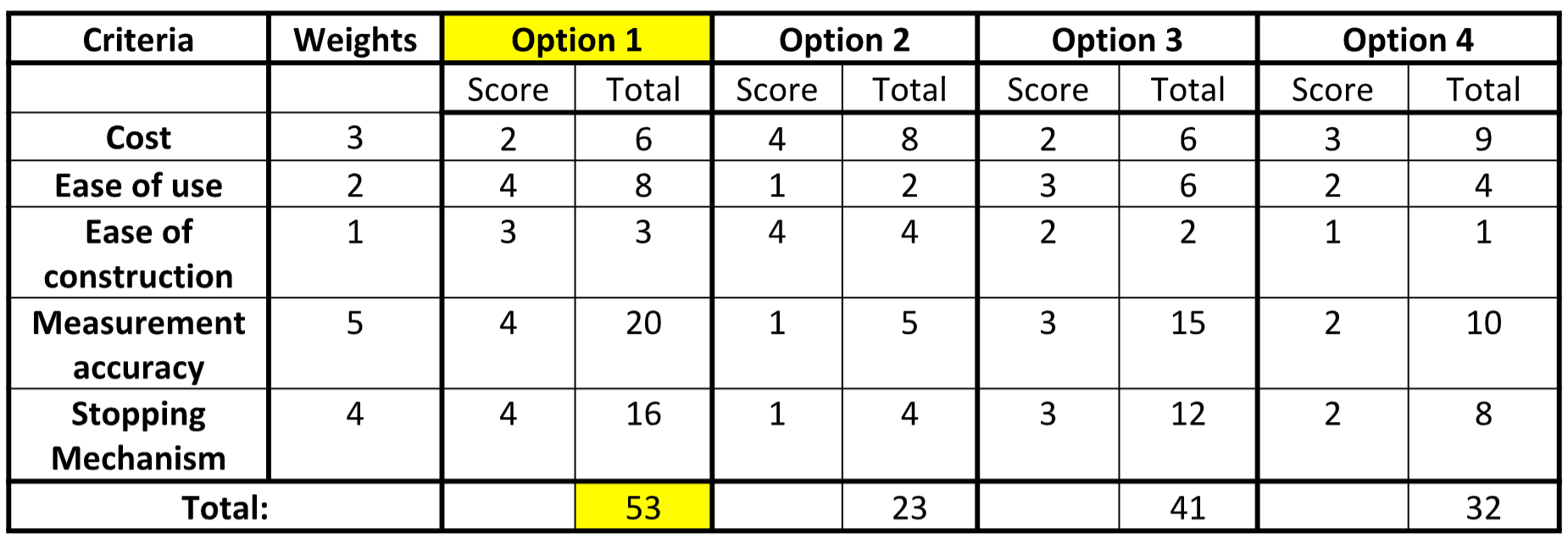
Options 1 and 2 in the matrix (below) are shown above. Ultimately, we decided to move forward with Option 1 as it had the highest weighted score of all the options, though the design ended up going through changes as we refined the hardware, CAD, and electronics.
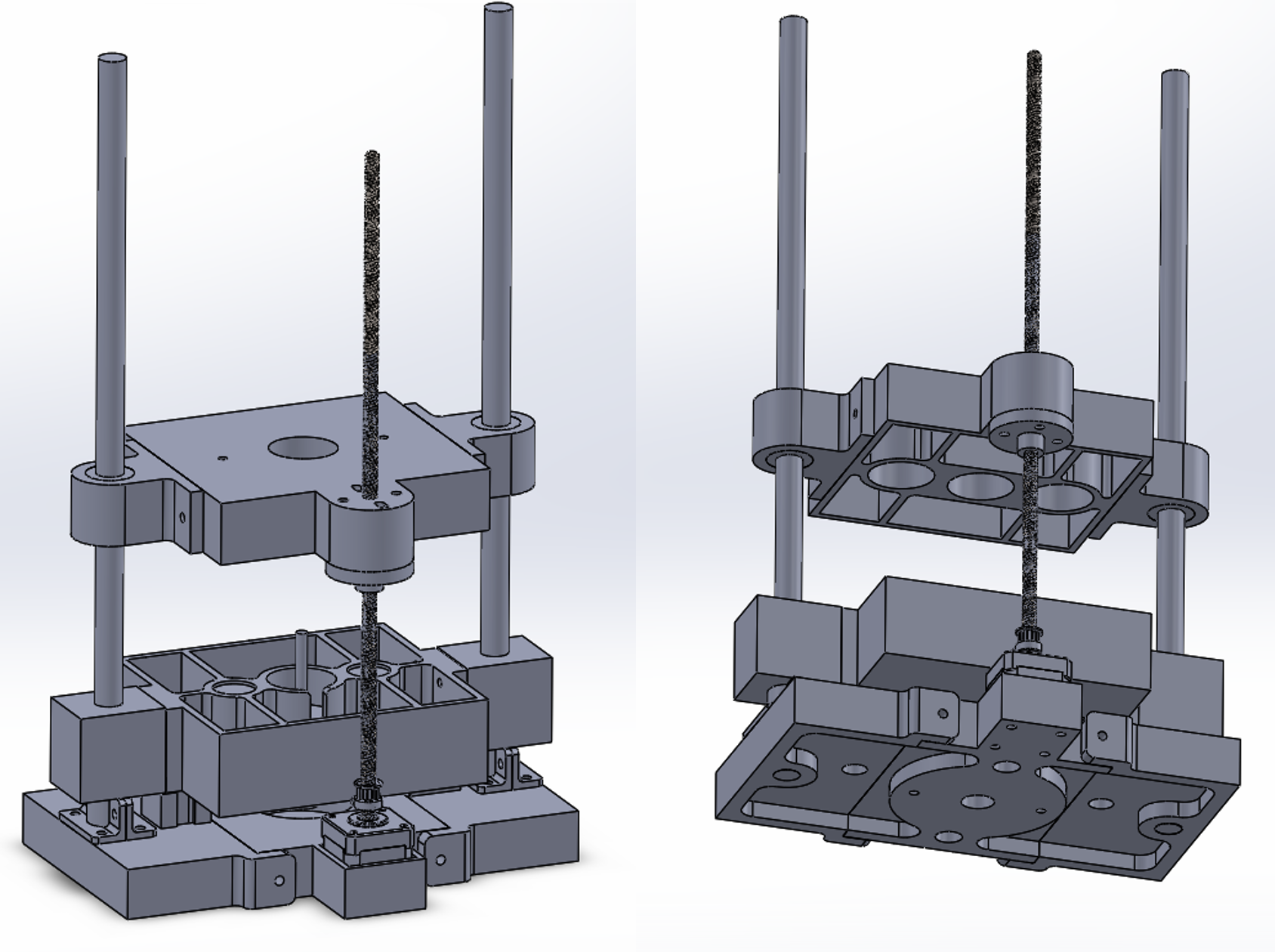
CAD
Between making the decision matrix and finalizing the CAD, we decided to forgo the cable idea in Option 1 (cables shown in blue), as this might introduce unevenness in platform levelling, require variable motor revolutions as the cable coils build up thickness around the shaft, and necessitate complex electronics such as a electromagnetic clutch for the motor.
Instead, we introduced a “picker-upper” platform embedded with electromagnets that would attract magnets in the impactor platform and pick it up to the desired height. The voltage supply is then cut to release the impactor platform magnets, causing the impactor platform to free fall and impact the biological sample.
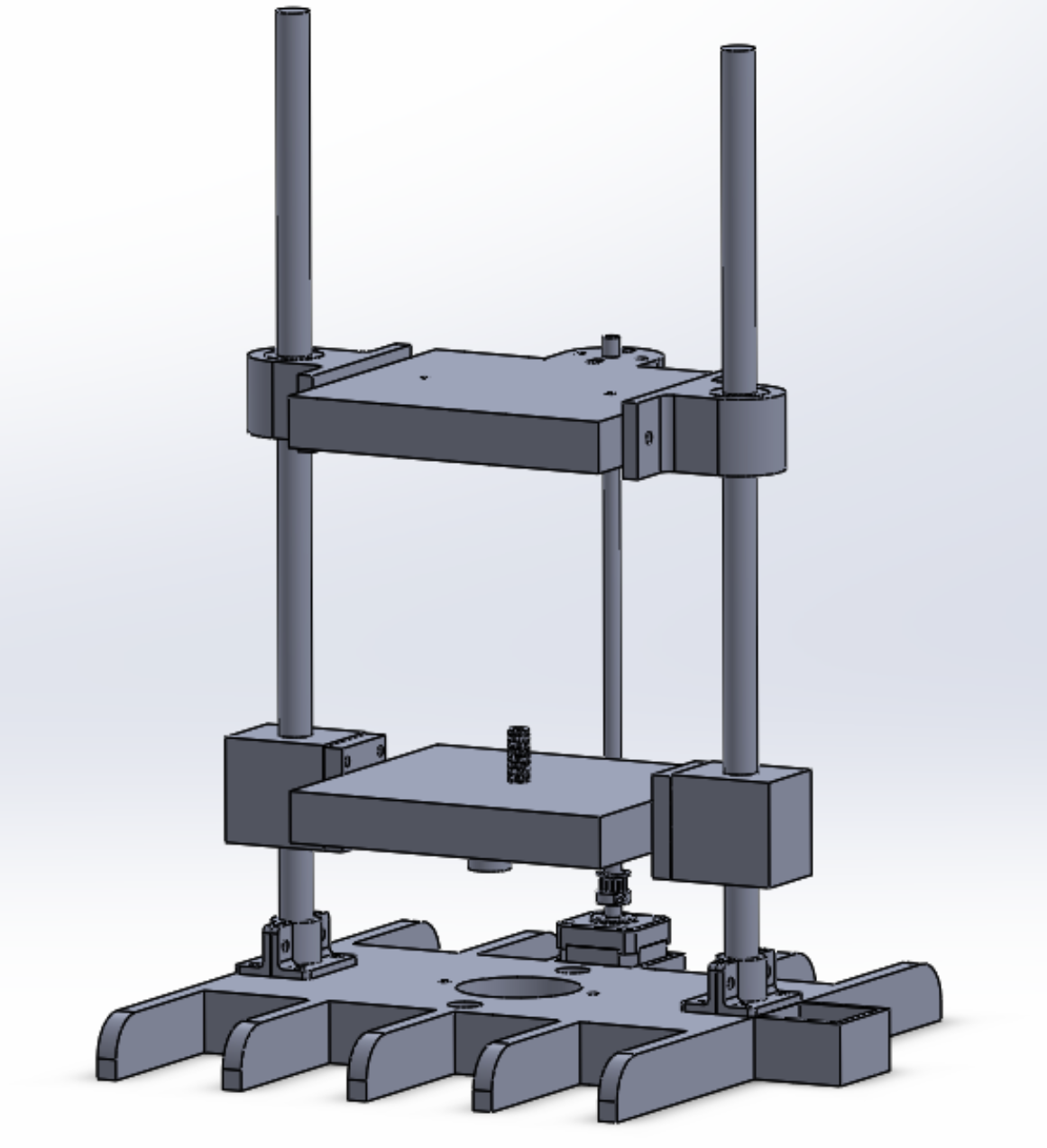
My first CAD version is below. It was an initial CAD containing most of the hardware and electronics we wanted, but not yet optimized for manufacturing and assembly.
The next iteration was designed with DFM and DFA in mind. I CADed everything as if it were to be injection molded, with constant-thickness walls, ribbing (for strength), and cavities (to minimize material). For assembly purposes, I split the base into three parts that could be located to each other and screwed together (the entire base was too big for the print bed).
Electronics
The electronic components consist of the following:
→ Force transducers: to sense initial impact and read force values in biological sample
→ Solenoids, 24V: to stop secondary impacts from the impactor; will actuate after initial impact is sensed by force transducers
→ Electromagnets, 5V: to pick up the impactor platform
→ Arduino Uno, 5V: to tie electronic components' signals together
→ Lead Screw Motor, 12V: To precisely lift up picker-upper platform to desired drop height
Finite Element Analysis (ABAQUS)
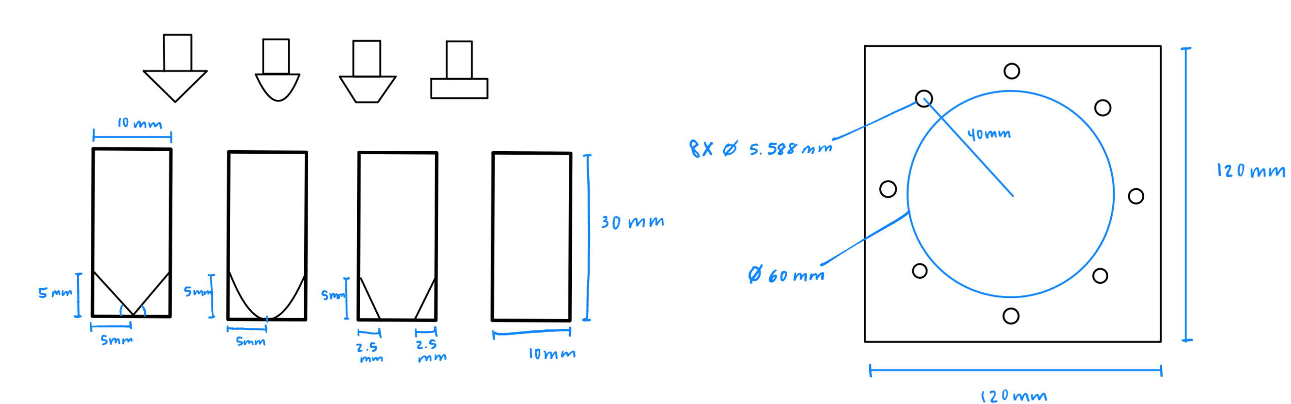
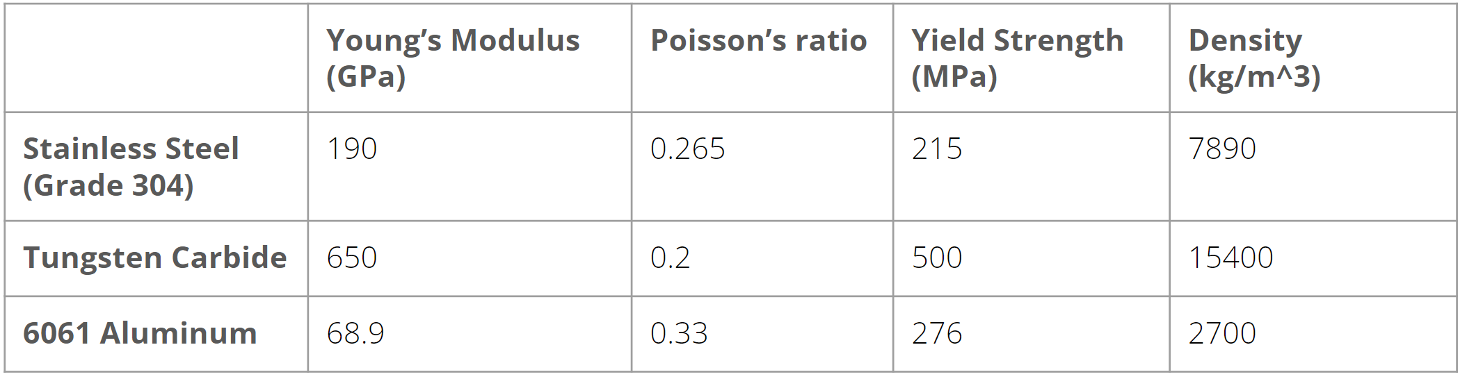
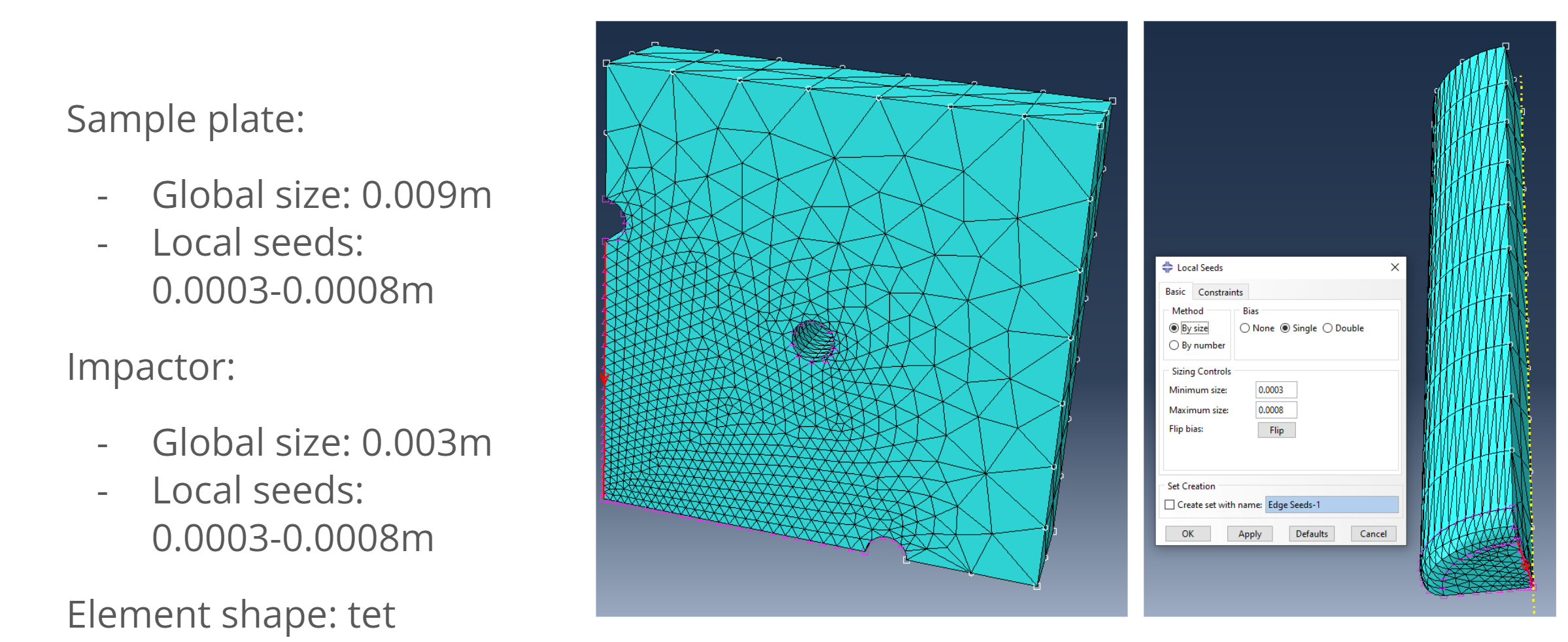
I performed an extensive finite element analysis in ABAQUS to optimize the design of the impactor geometry. I modeled 4 different impactor geometries: triangle, circle, trapezoid, and square. For the sample plate, I based the design off existing metal samples used in drop tower tests. The assembly exhibited quarter symmetry, so all the parts were modeled as 1/4 of their full design to minimize simulation run time (from 90 min to 15 min). I tested 304 stainless teel and tungsten carbide for the impactor, and 6061 aluminum for the sample since aluminum is stronger than the strongest biological sample (bone, yield strength 106-131 MPa in compression).
- Model the parts
- Define material properties, assign to parts
-
Create instances
-
Create an Explicit Dynamic step (Time Period = 0.0005s, Frequency = 30)
-
Set Interaction Contact to be Hard and Frictionless
-
Load: impactor initial velocity is -2.426 m/s (v = sqrt(2gh), with h = 300mm)
-
Boundary Conditions: reflect quarter symmetry and sample plate clamping
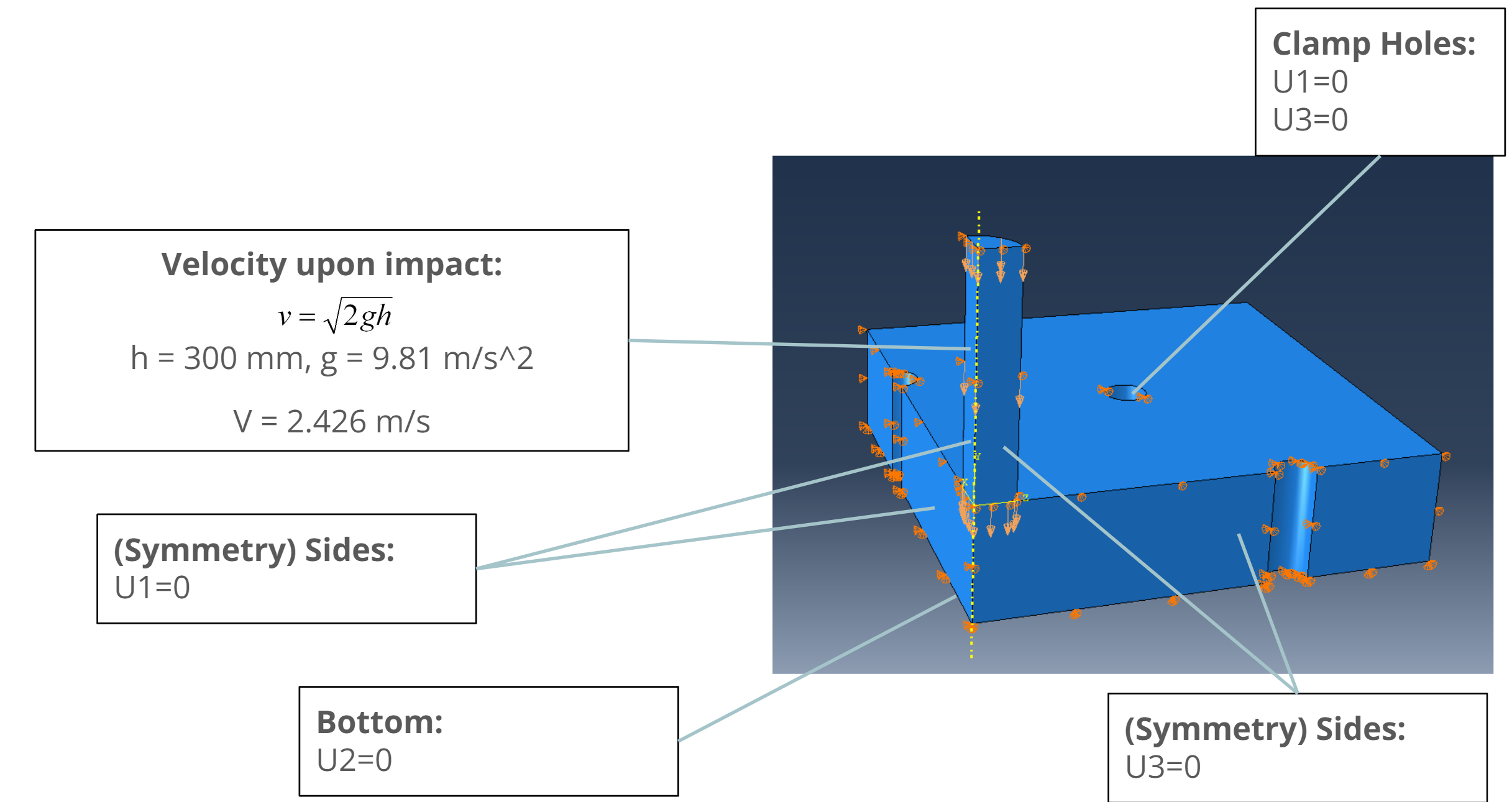
- Mesh: tetrahedral elements (higher meshing accuracy, good for observing fine dynamic deformation); finer mesh around impact areas (0.0003m)
Results:
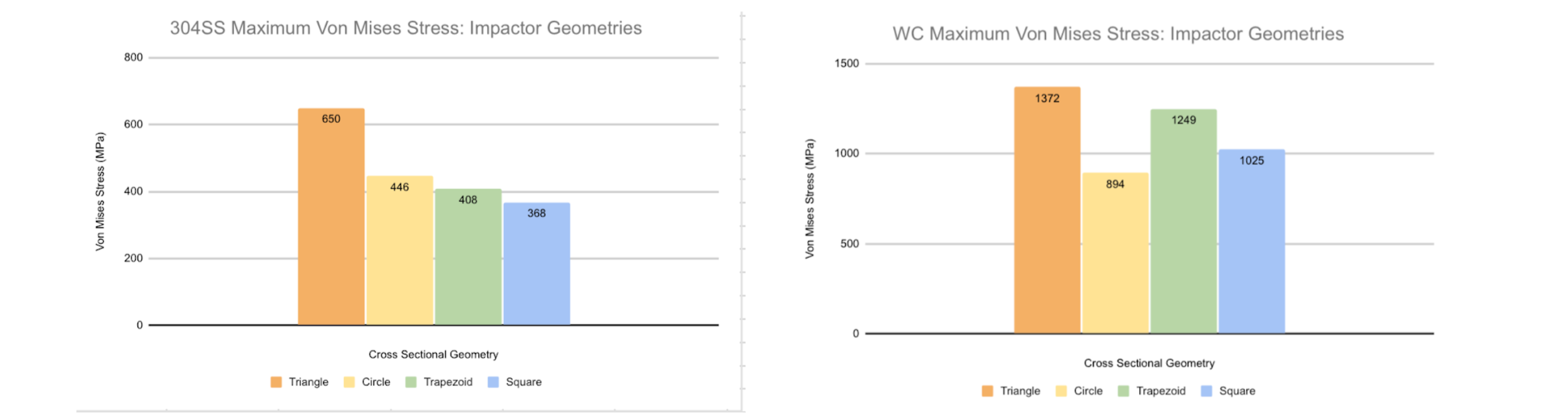
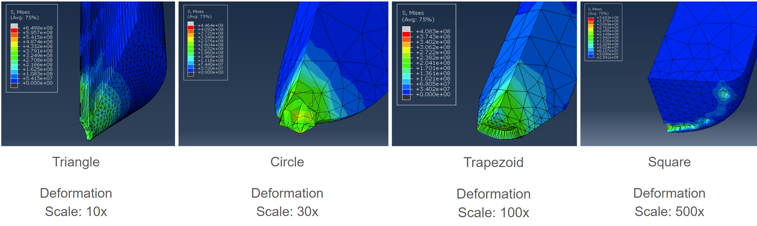
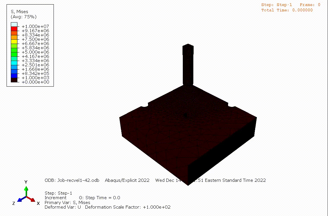
In conclusion, we observe that geometries with a larger “point” at the impactor head experience greater Von Mises stresses upon impact compared to flatter geometries like the square cross section impactor. The maximum stress that the square impactor experienced was 57% of what the triangle impactor experienced. Thus, to maximize the load that a drop tower impactor can withstand, the impactor head should be as flat as possible while avoiding sharp edges.
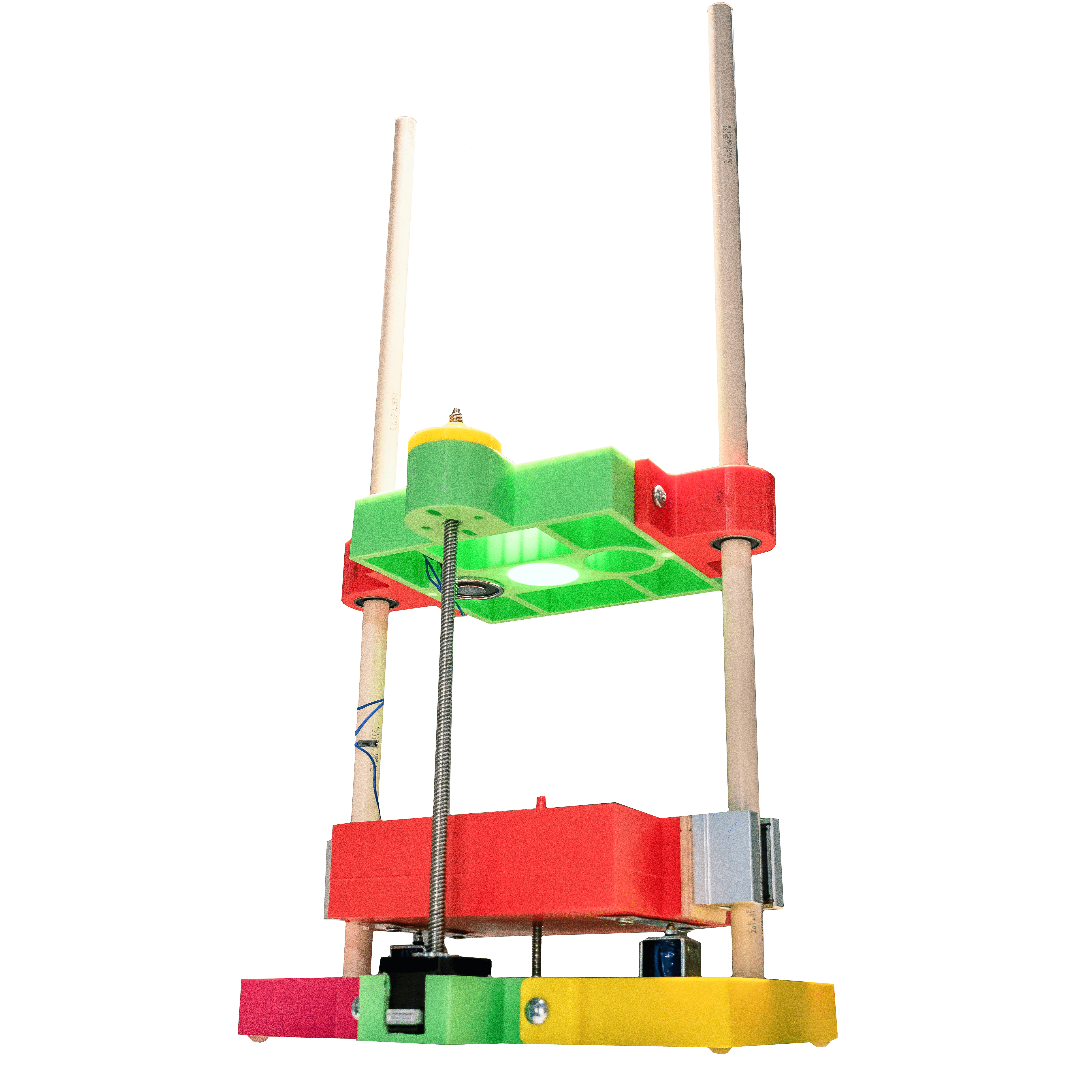
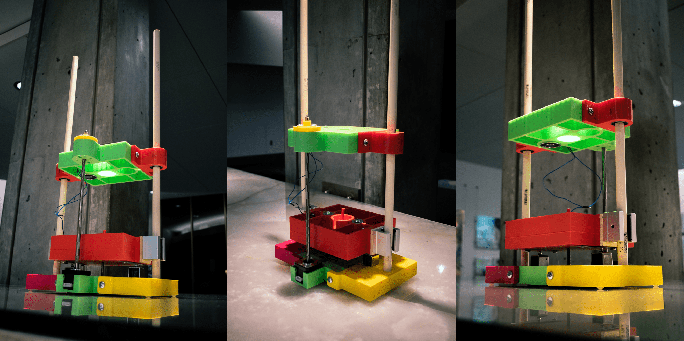
Final Product
We didn’t have enough time left in the semester to complete the functionality of all the electronics, but next steps would be to have the electronics communicate with each other in Arduino and possibly LabView (force transducer readings). For now, here is a video of the lead screw working:
… And here are some final product images I took and edited:
Thank you for reading!