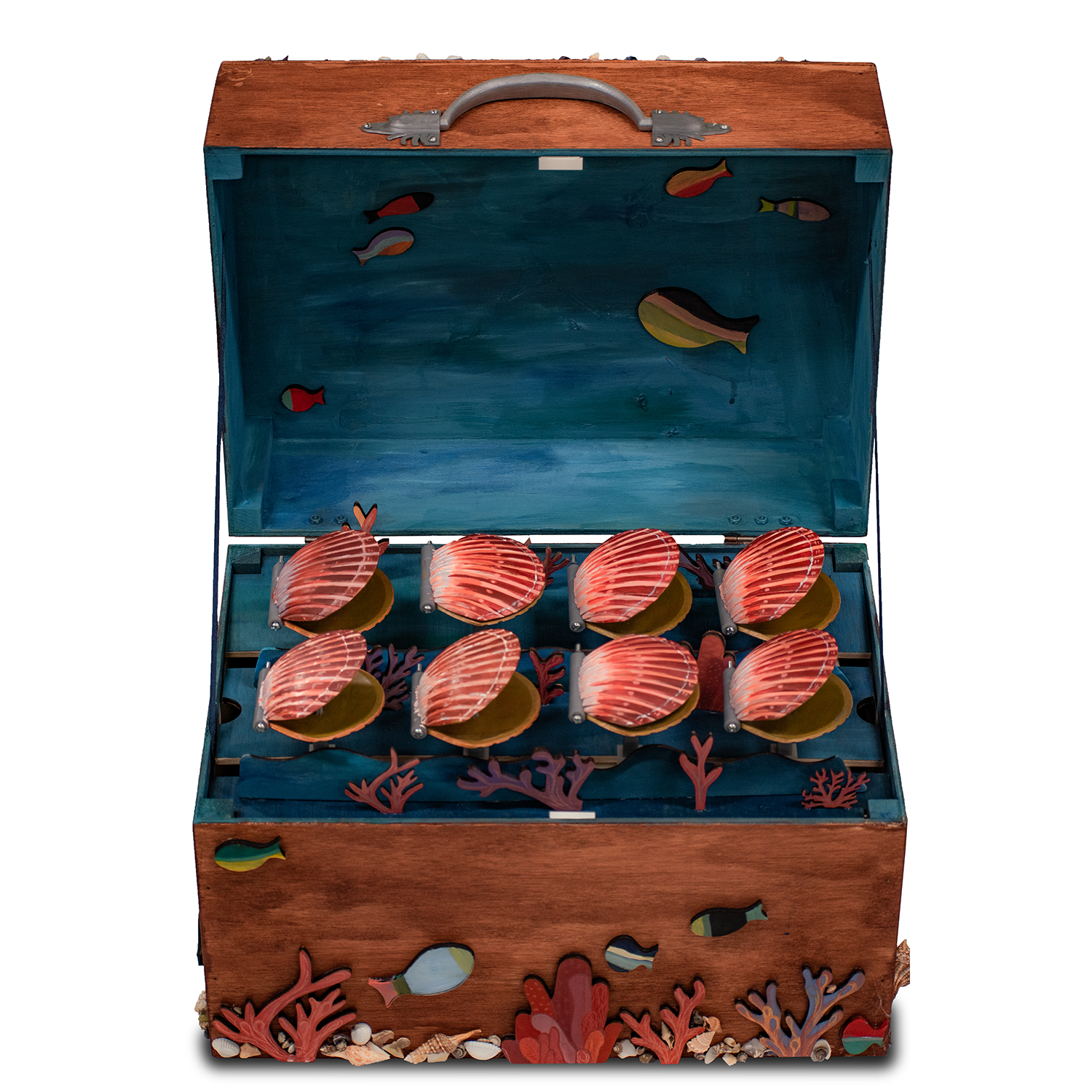
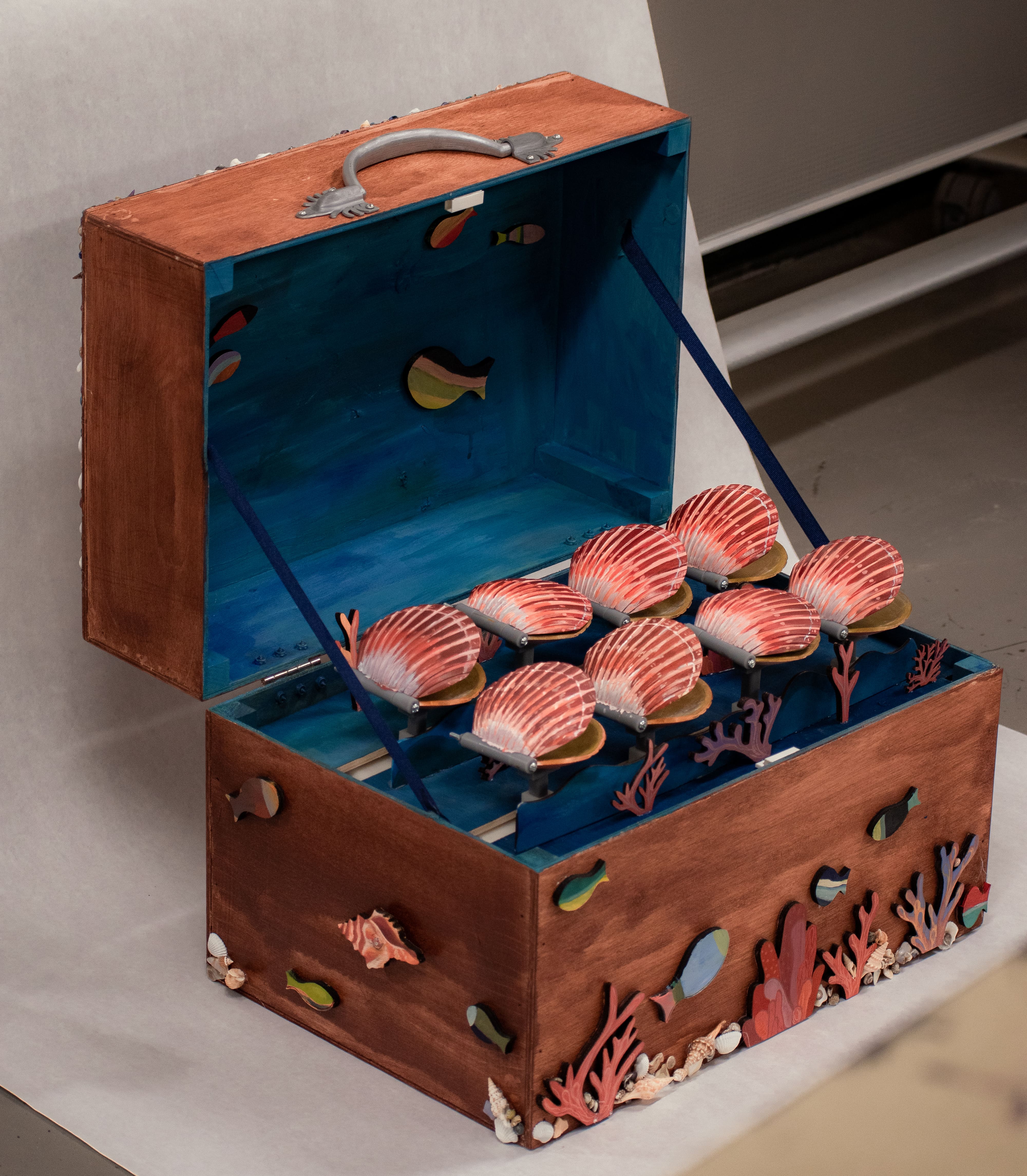
Scallop Music Box
The swarm scallops project aims to raise awareness of human interference on natural habitats and environments, negatively impacting sea life such as scallops. Scallops are one of few shellfish with the ability to swim, but, observed in their natural habitats, they do so sparingly and leisurely. It is only when they are being fished that they swim quickly. The viewer, through their interaction, gets to decide the context of the piece: are the scallops swimming in their lush beds of eelgrass, or are they running frantically, fighting for their survival? Turn the knob and the stakes rise.
This project was done in Fall 2021.
Brainstorm
We began by sketching high-level ideas for the scallop motions we wanted to emulate. A figure-8 motion, opening and closing of the mouths, and the up and down wave motion were our initial goals.
We realized that – considering our space and budget constraints – we could have at most two of the three motions we wanted (having more than two mechanisms would be too tight to fit in our size constraints). We decided to move forward with (1) the opening and closing of the mouths and (2) the up and down wave motion.
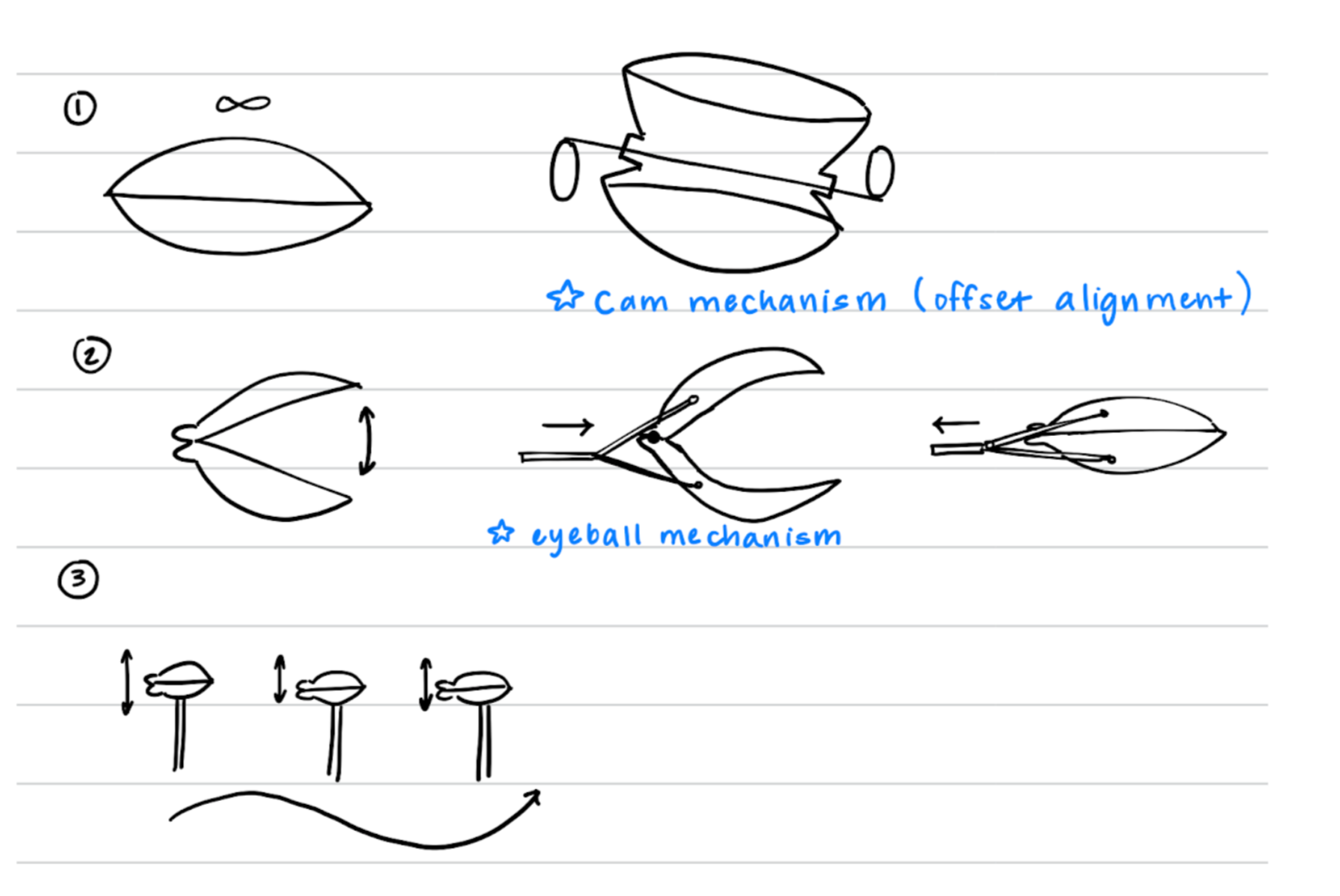
Then, we started to brainstorm more lower-level mechanism designs. For our design decision-making, we chose the design that would minimize the number of parts and the complexity of the mechanism. We decided to move forward with Mechanism 1 (see image below) due to its simplicity and minimization of parts (reduced cost and friction).
Mechanism Iterations
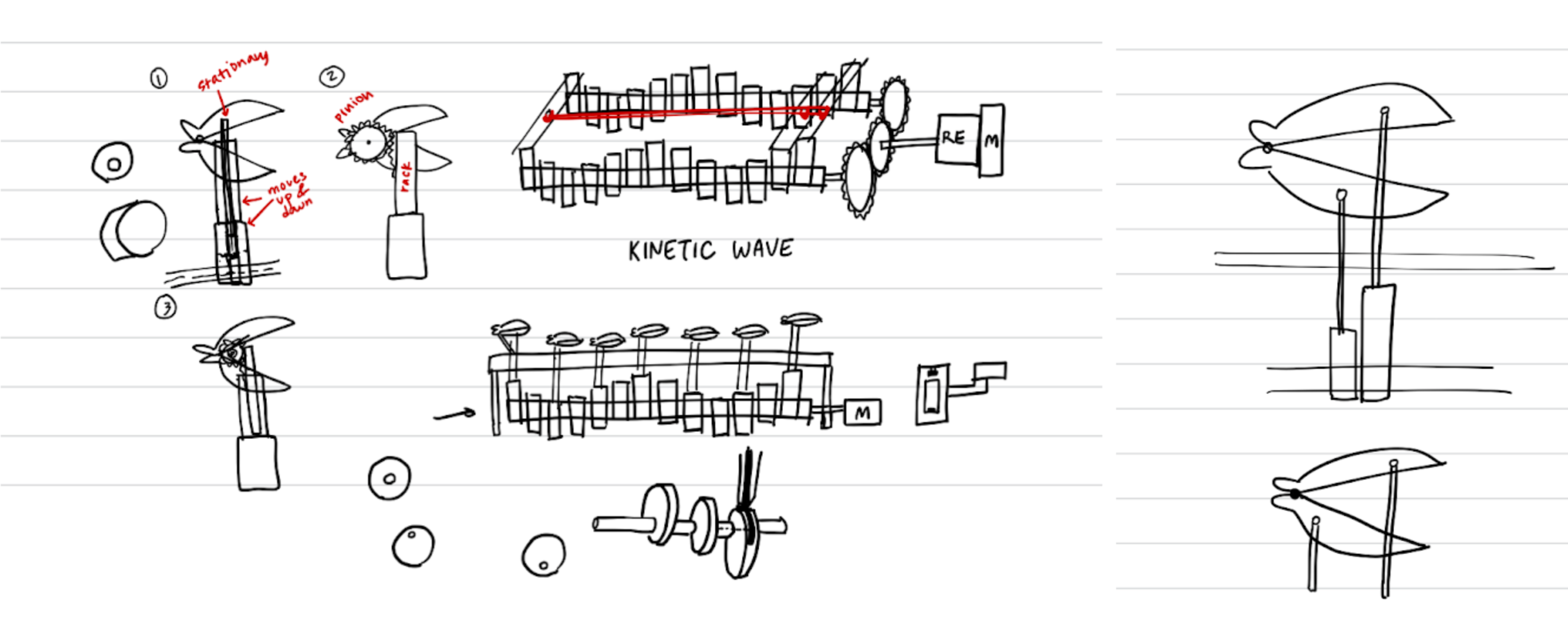
Our mechanism prototyping process looks like the following (left to right: general cam mechanism, single scallop mechanism, four-scallop module):
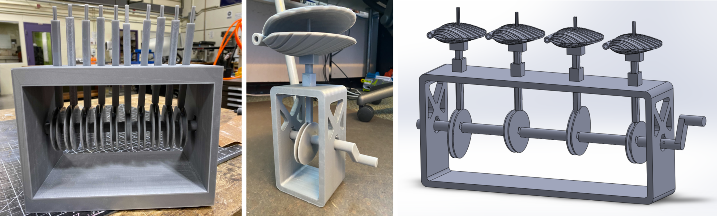
For the general cam mechanism, we wanted to see if the general idea of the mechanism was functional. After some sanding, we observed that the mechanism worked but could do with improvements.
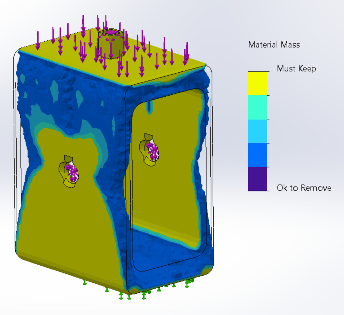
For the single scallop mechanism, we removed unnecessary material from the general cam mechanism after running a topological analysis in SolidWorks. We introduced the scallop model. We also tested multiple cam profiles to determine which ellipse major axis performed the best (the tradeoff between having a higher wave peak height vs. minimizing the torque required to turn the mechanism). The best ellipse major axis was 90mm.
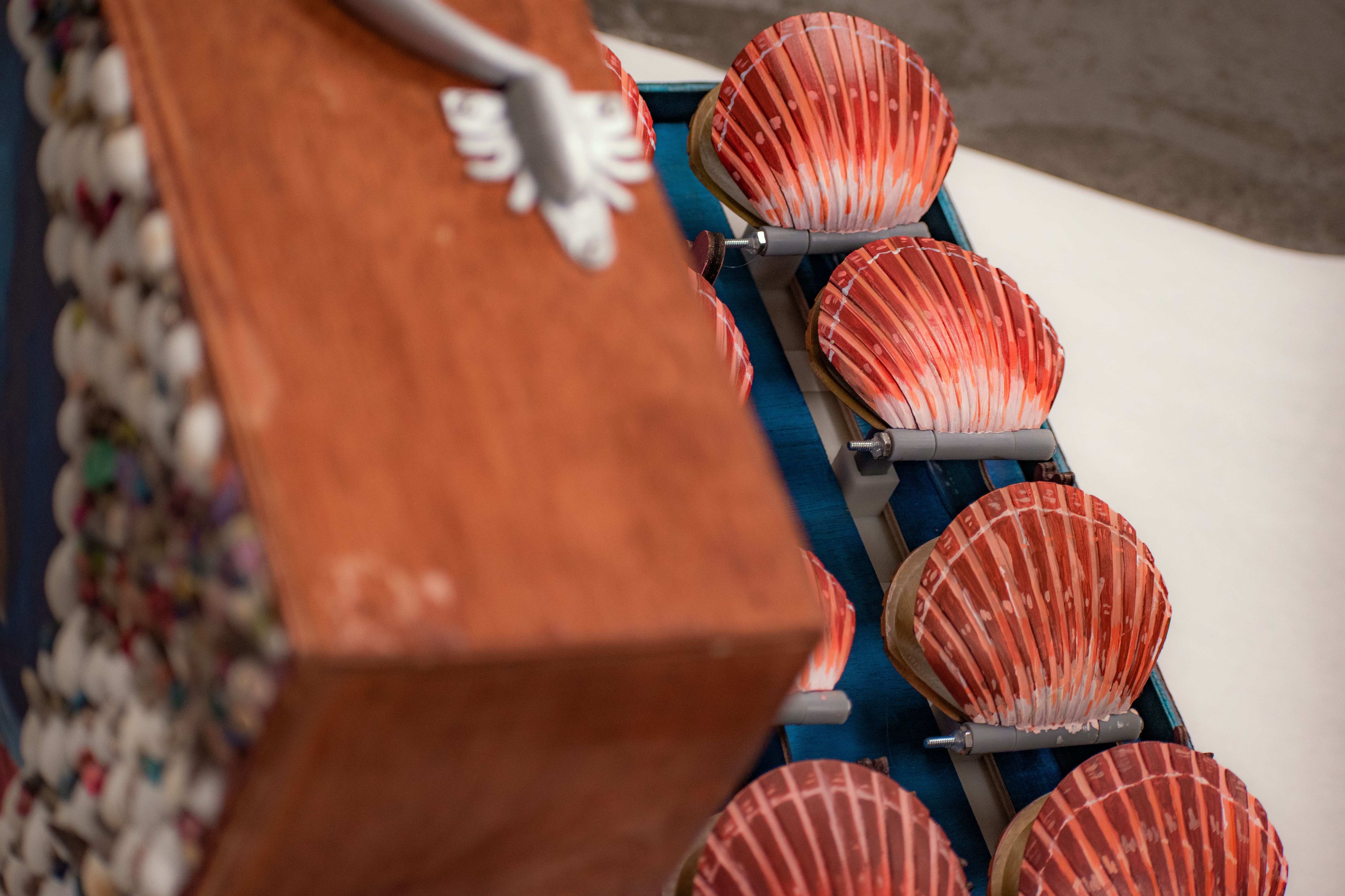
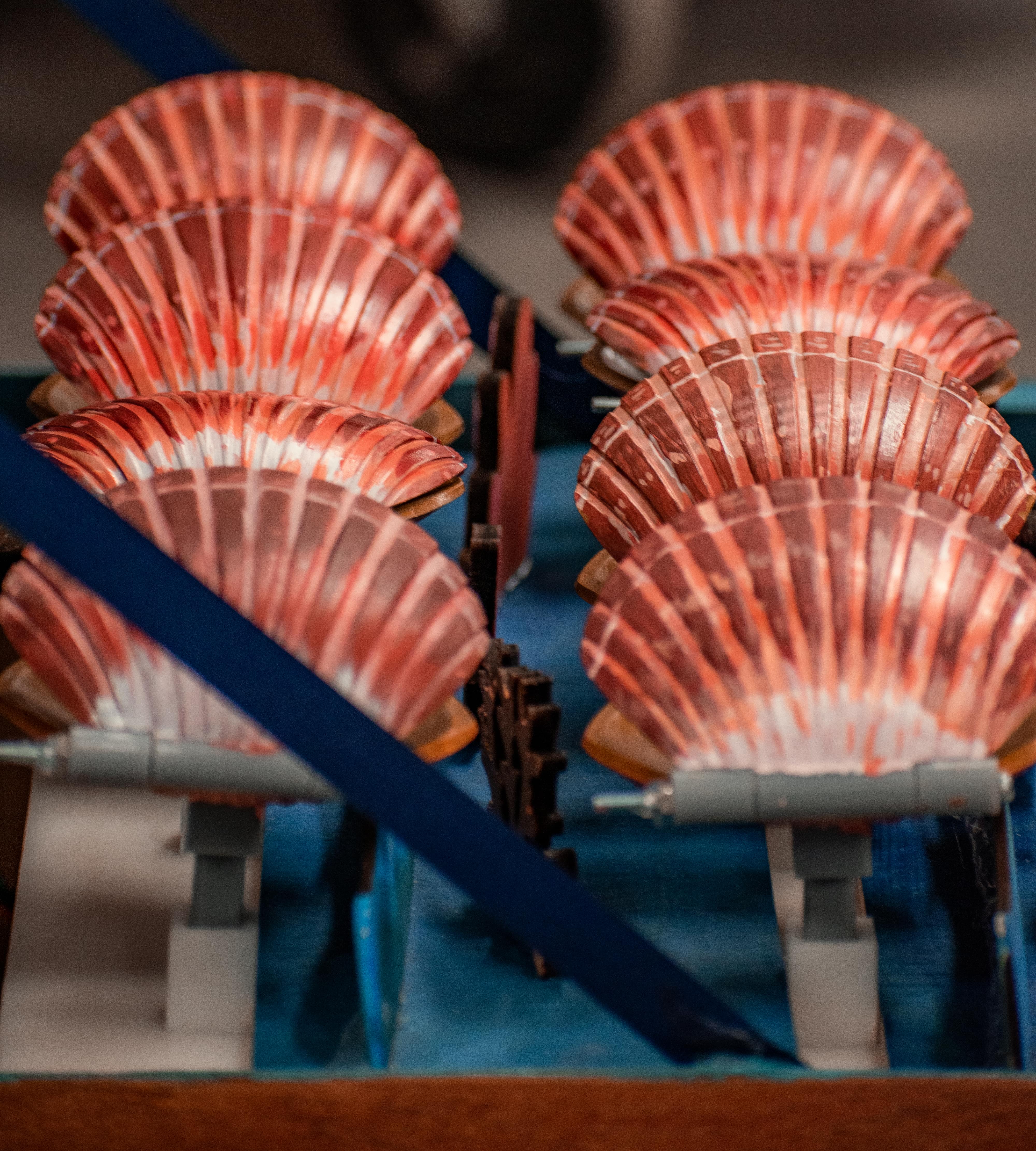
The four-scallop module was the single scallop mechanism but multiplied. Some minor design changes were made to improve from the single scallop mechanism (scaling the scallops down by 40%).
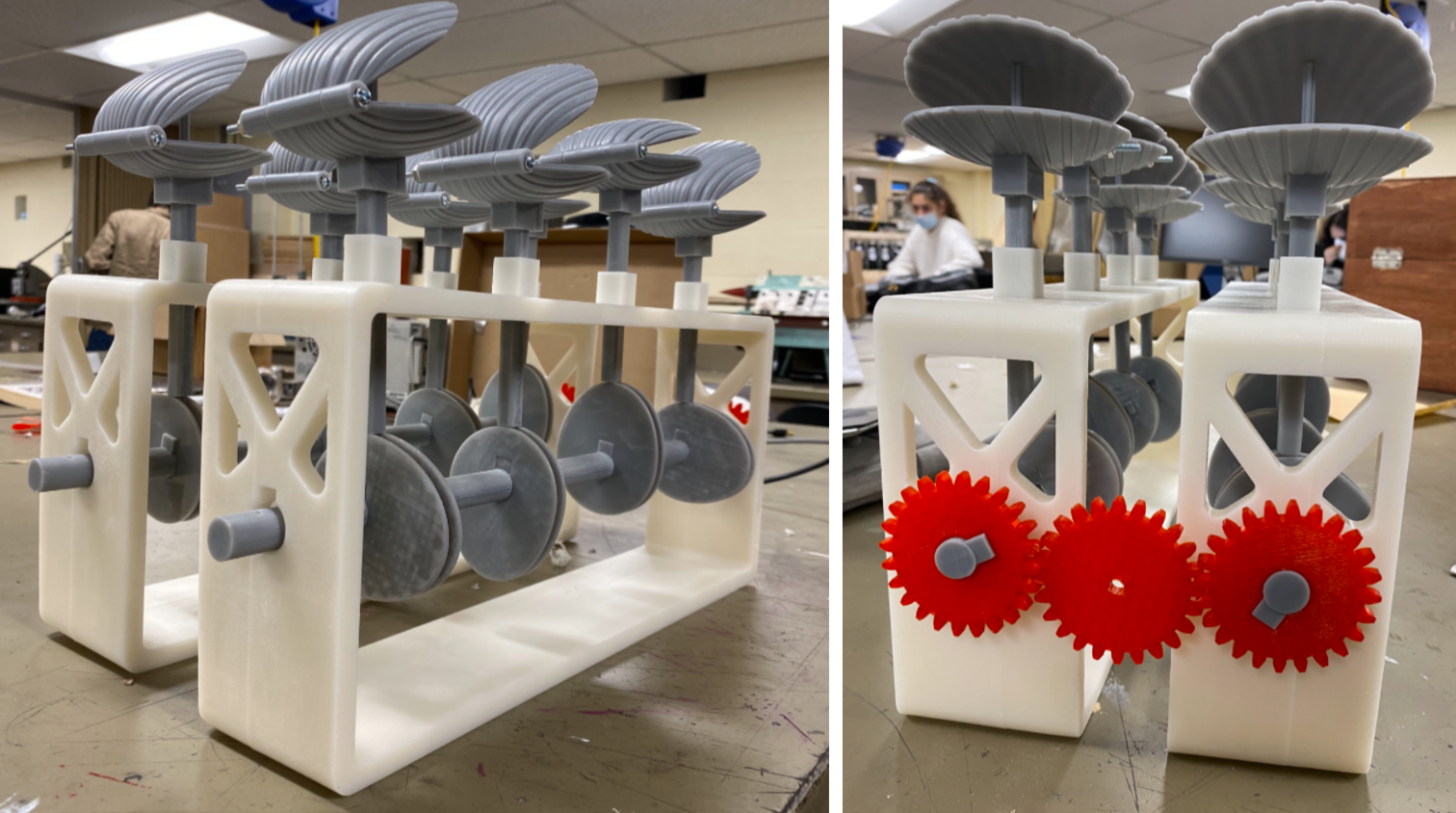
We used two of the four-scallop modules for a total of eight scallops. To connect the two four-scallop modules, we attached gears at the ends of the modules’ central rods and had a center gear attached to the stepper motor. The stepper motor would then power both of the modules at the same time.
To make the gears, we used a gear maker add-in called SpurGear in Fusion 360. The gears had a diameter of 304.55mm and 24 teeth.
Box Making
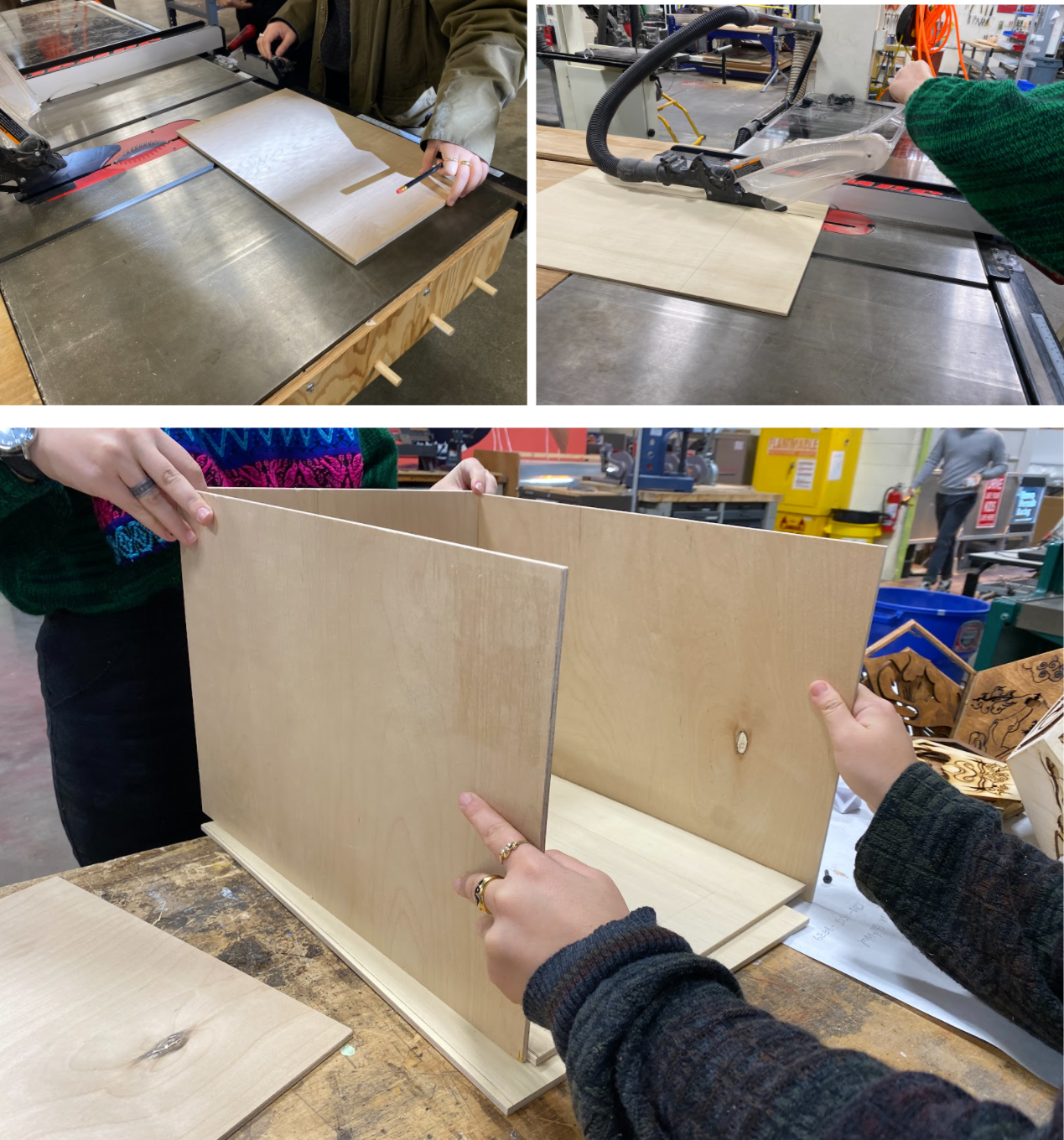
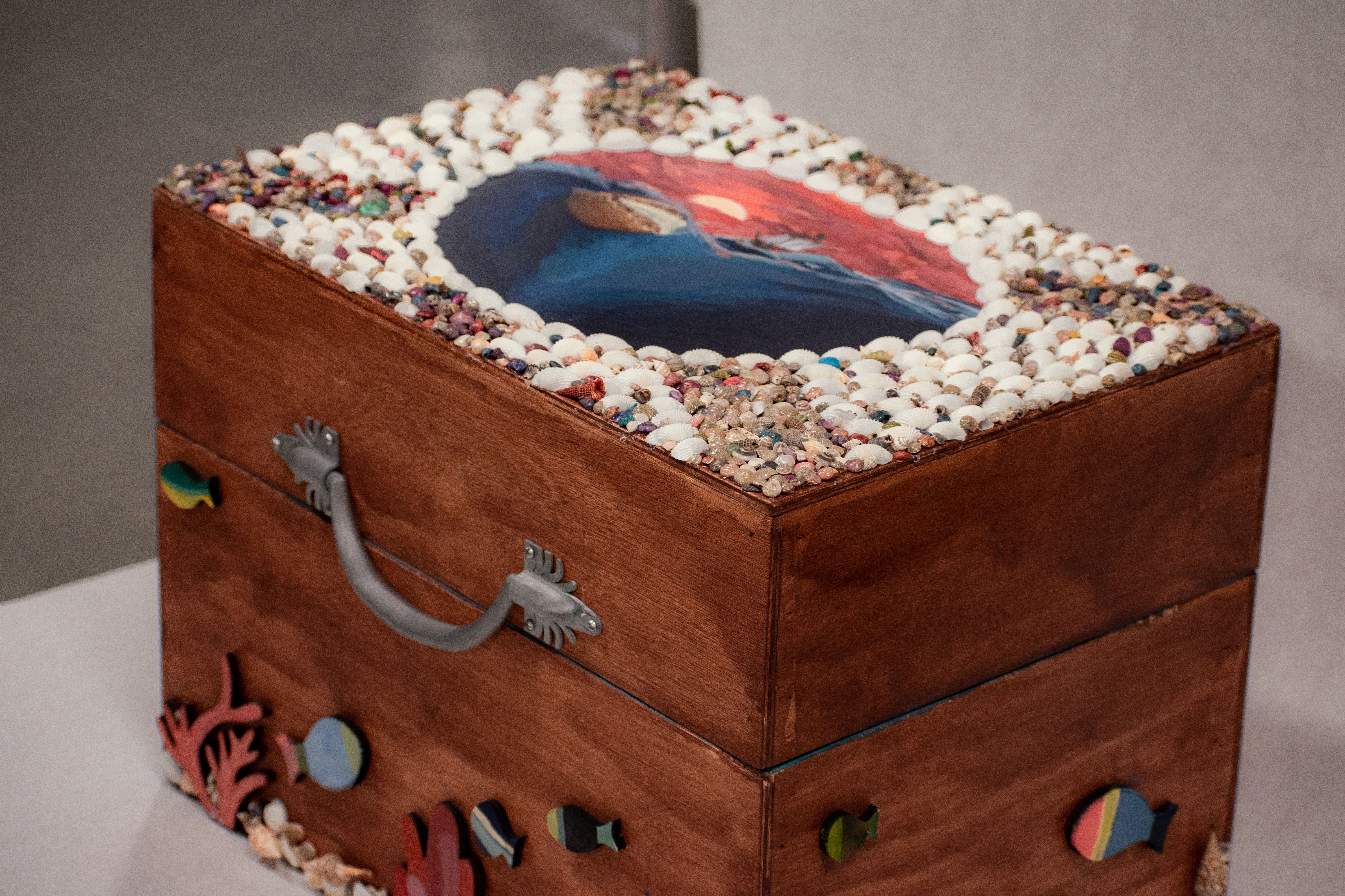
We constructed the box using birch plywood and pine. We dimensioned the box to cover the cam mechanism frames and the motor with enough room for the box to clear the tallest point of the scallop. The box was assembled by using wood glue to adhere the plywood to the pine ribs and then pinned into place with a brad nail gun. Hinges were installed with screws to allow the box to open and close.
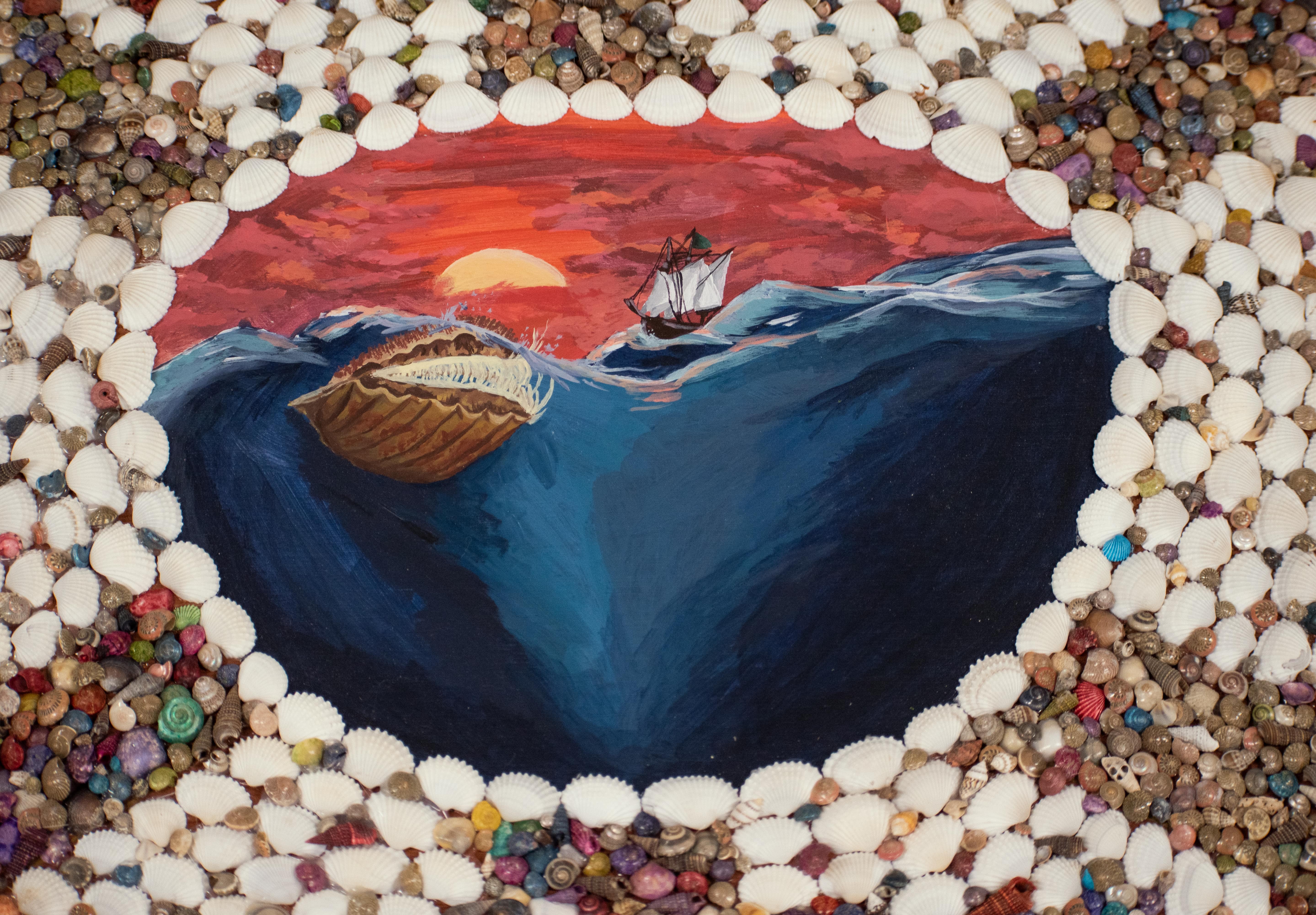
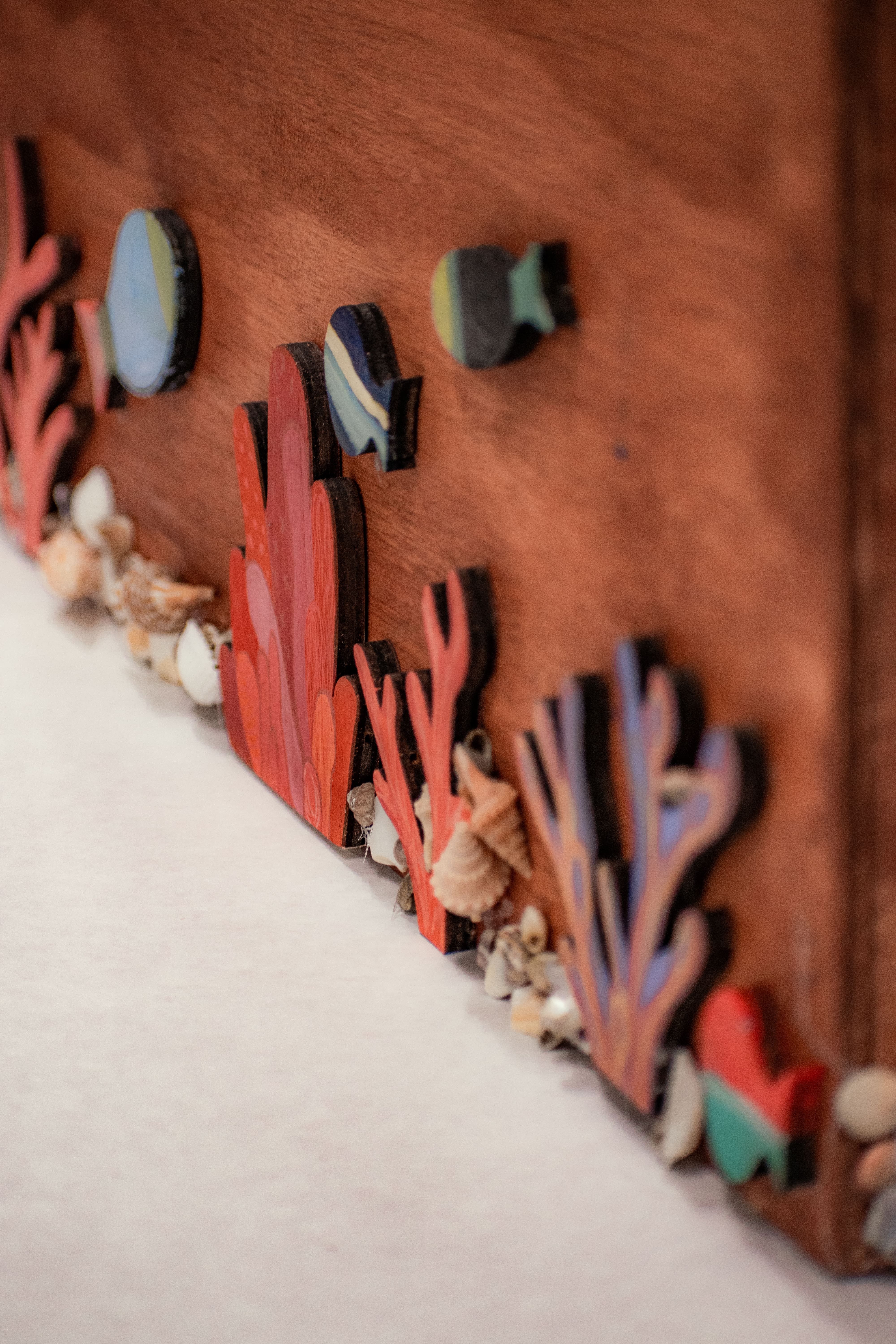
The box is then stained with a walnut dye, drilled with holes for the potentiometer dial and speaker cord, decorated to look like a Victorian sailor’s valentine box, and assembled with sensors in optimal positions.
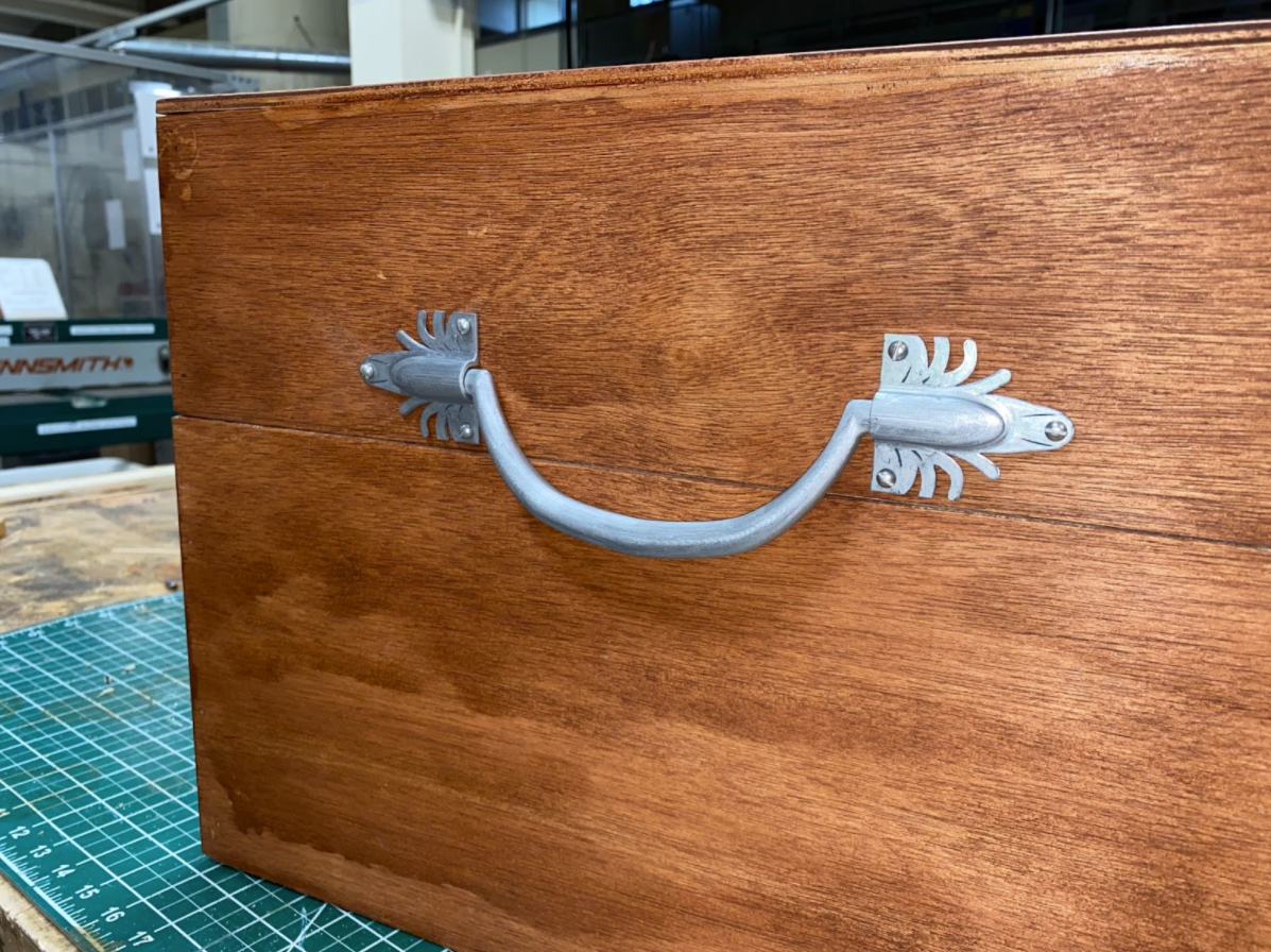
We wanted to add a handle to the box to make it easier for users to interact with it.
We imported a GradCAD file of an old-style handle (https://grabcad.com/library/handle-old-style-1) into SolidWorks and modified it, using the middle handle in the image below for inspiration. We then 3D printed the handle out of resin and coated it with reflective ink.
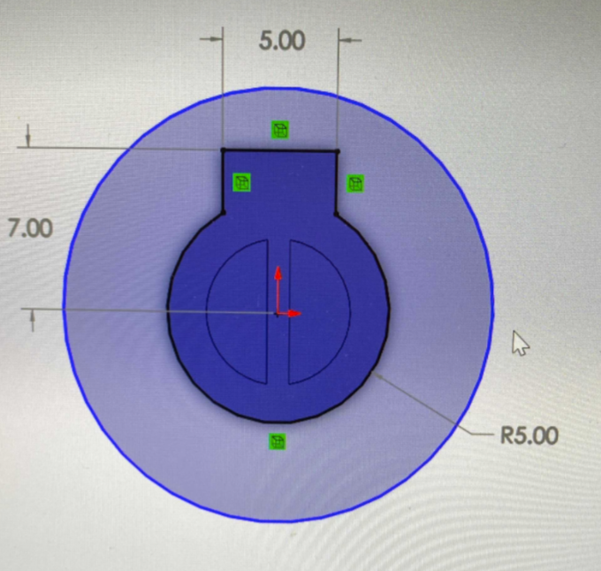
Potentiometer
We made an adapter piece for the potentiometer so that we could more easily design the knob around the adapter. Different versions of the adapter piece were 3D printed. The dimensions of the adapter are shown below:
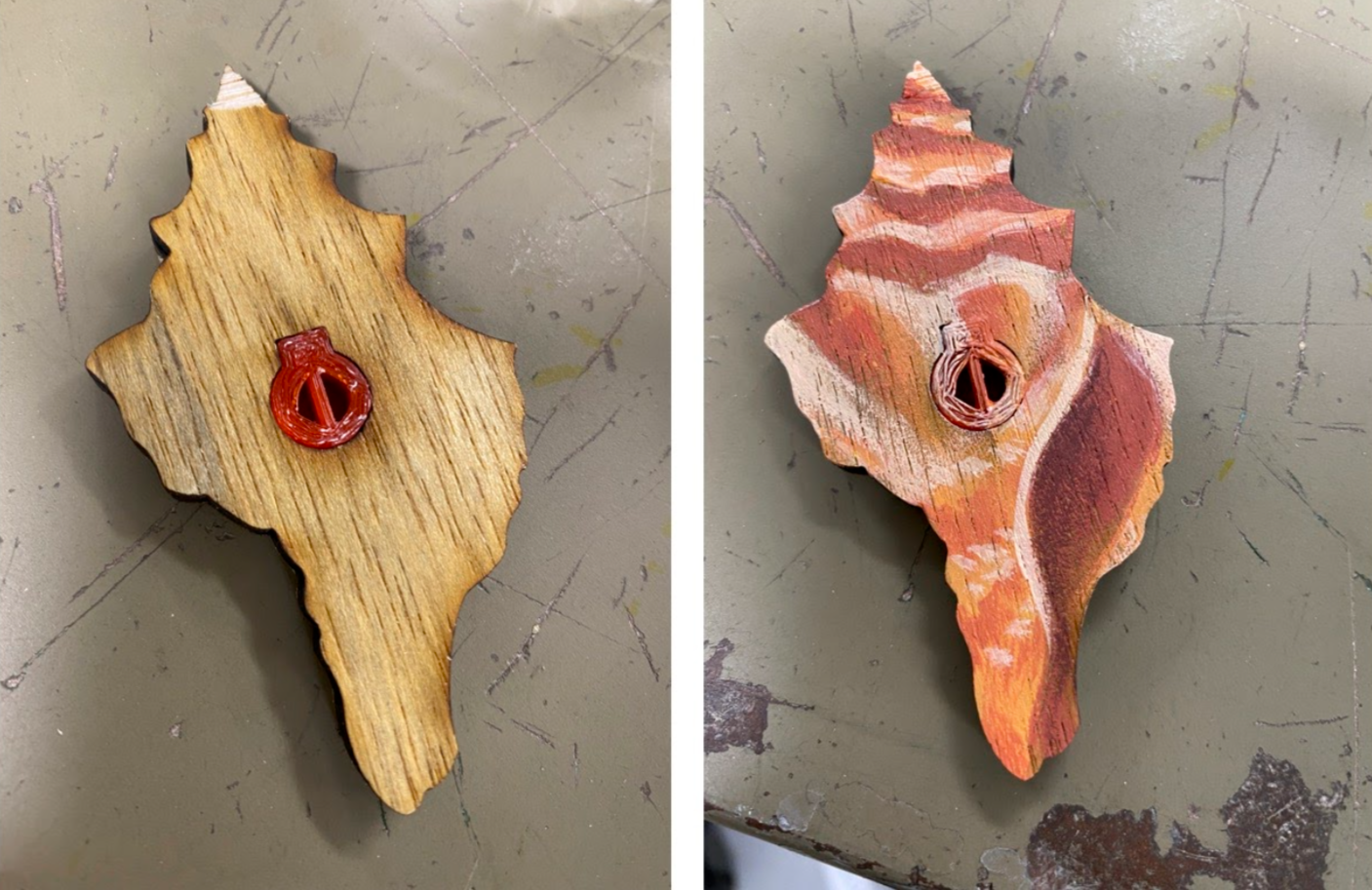
We decided on one of the adapter designs (used in the photo below). We then designed a seashell knob around the adapter piece. The seashell knob was designed in Adobe Illustrator, laser cut, then painted to look cohesive with the rest of the scallop box.
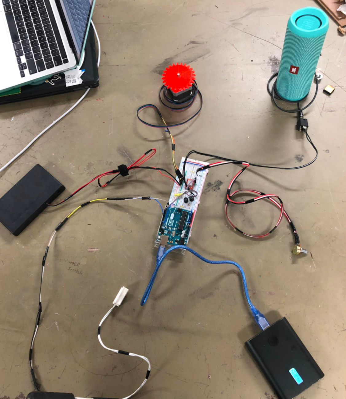
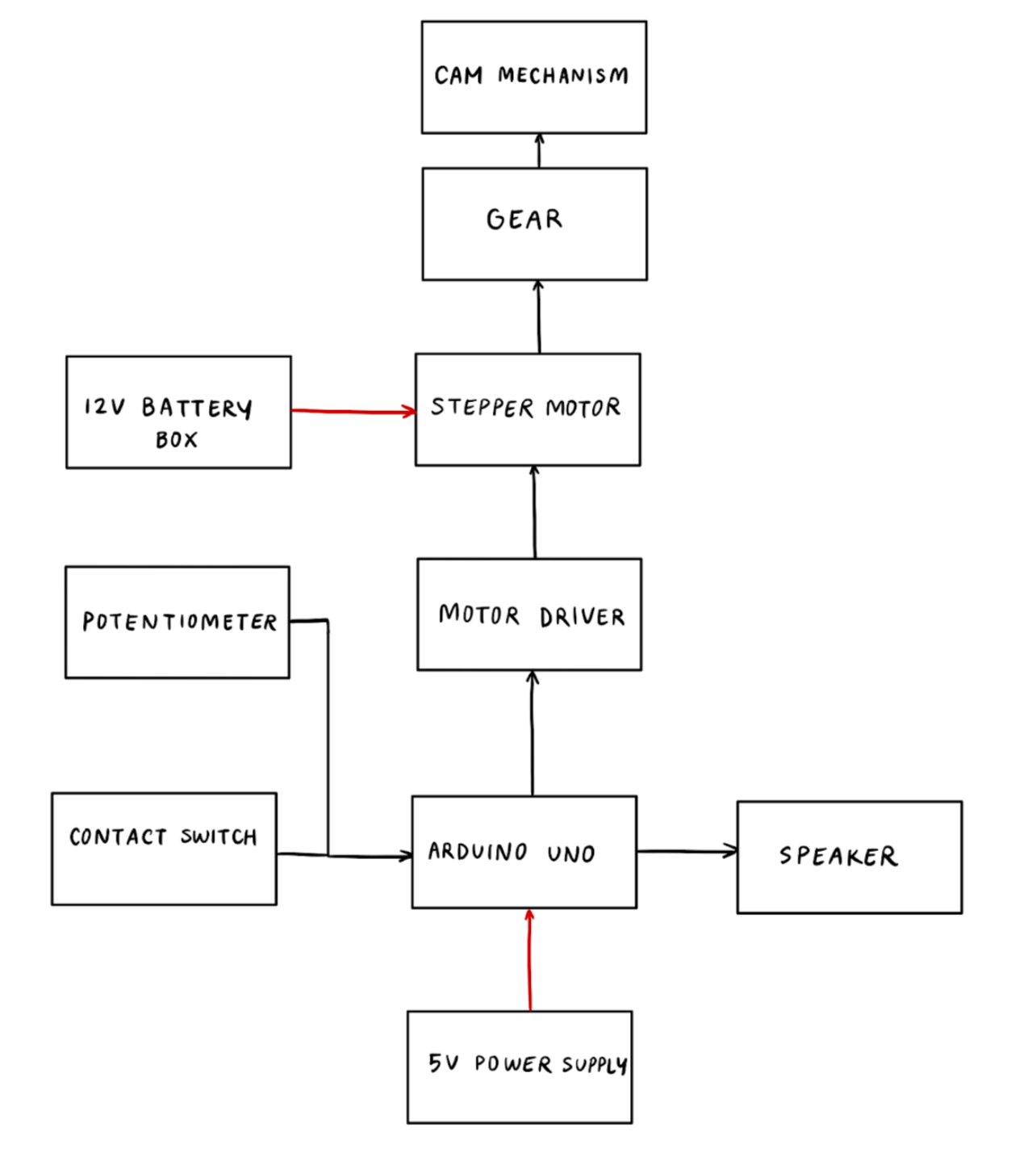
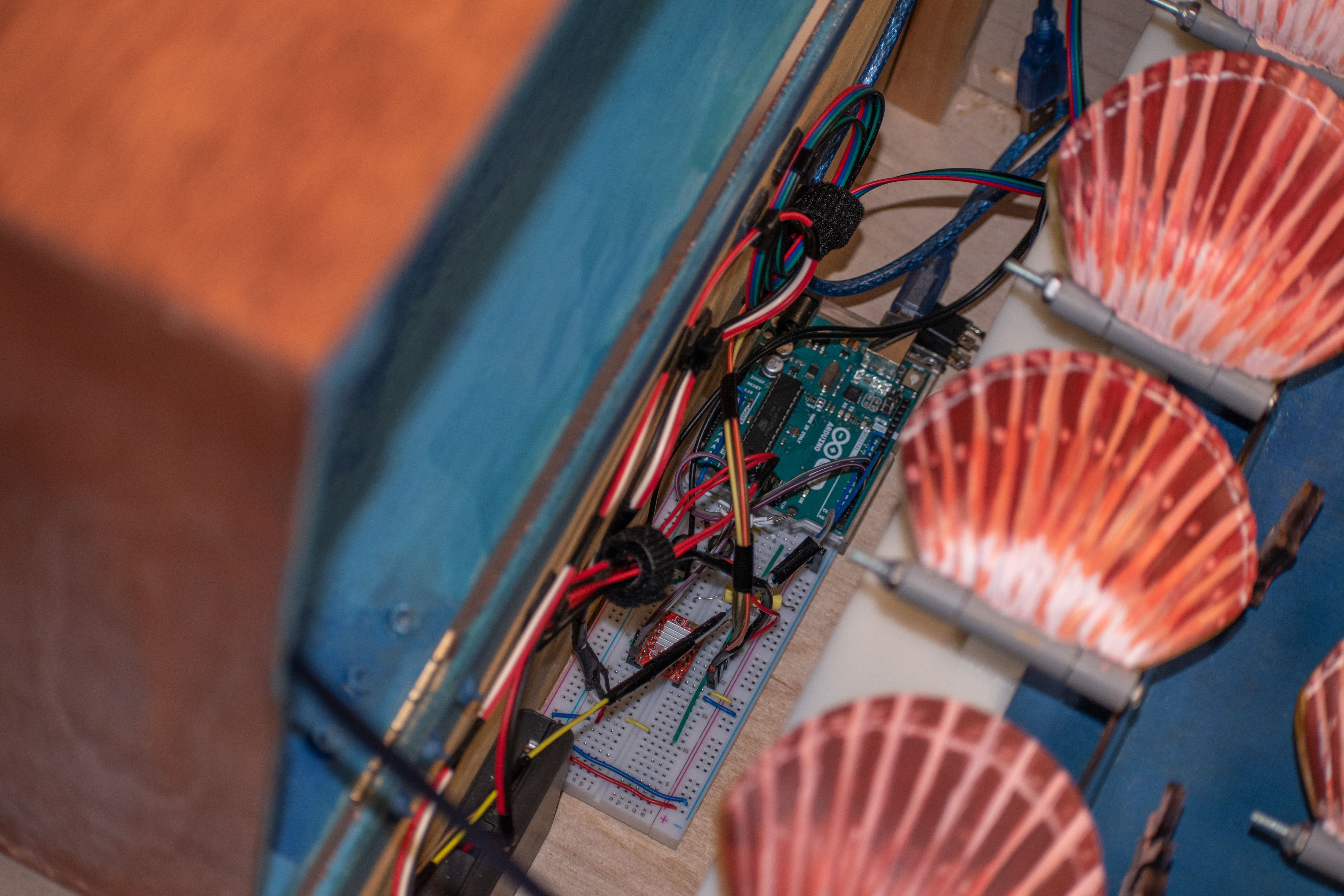
Circuitry
Each component is connected to and controlled by the arduino and is connected to its needed power supply. All the logic and interactions between components are controlled by the Arduino Uno through software. The different components are powered by a 5V power line through a power bank connected by a USB cable to the Arduino connected to the circuit, and a 12V power line supplied by 8 AA batteries wired in series. The 5V power line is supplied through the Arduino’s inbuilt 5V and ground pins which are linked to the breadboard’s positive and negative channels then routed to components as needed. The 12V power line runs directly to the motor driver’s VMOT and GND pins as the motor is the only component needing 12V power.
Arduino
Motor
The motor code is run using the Stepper.h library, and calls the motor to move in each loop() iteration using the stepper.step(20) function call. The initial speed is set to 50, and is modified by the potentiometer whenever a change in the potentiometer value is detected.
Potentiometer
The potentiometer was used to control the speed of the scallops via the motor, as well as the speed of the music. It had a range of 0 - 1024 for the values received by the analog input pin of the Arduino, of which we utilized 1 - 1000 for the sake of simplicity and easy conversion between music speed and motor speed.
Contact Switch
The contact switch was used to turn the whole circuit on and off and was attached to the front interior of the box. When the user opens the box the magnetic contraption inside the switch becomes disconnected, thus triggering the rest of the mechanism to come to life. Code wise, it operates much like a hall-effect sensor, returning a 1 when the magnets are separate and open and a 0 when the magnets are connected and closed.
MIDI
The initial MIDI Arduino code was supplied by our professor.
We wrote a Java program that would convert note letters to their corresponding frequency in a transcribed octave. After that, we entered in the note letters to Blue Danube by sight-reading the music including all the chords in treble-clef.
The Arduino code played The Blue Danube at varying speeds depending on the angle turned on the potentiometer. The notes for the piece were derived from musescore (link below) and converted into string letter notes by Vivian sight-reading them. These strings were then converted into numbers using a Java program.
https://musescore.com/user/27824718/scores/4941073
Overall Schematic Diagram
Calculations
Although our preliminary circuit functioned using the 5V stepper motor, the stepper motor (28BYJ-48) did not have enough torque to turn the whole mechanism. The 28BYJ-48 supplies 0.0805 Nm of torque. We ended up switching out the 5V motor in favor of a 12V stepper motor, which supplies 0.45 Nm of torque using an external power supply.
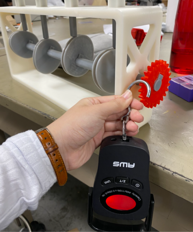
To determine the torque required to turn the central rod of the scallop mechanism, we attached a force gauge to the end of the motor gear and spun it. The torque required to turn the mechanism varied at different points of the cam orientation, from 0.0623 Nm to 0.2492 Nm. These values are calculated by using the torque formula:
Torque = Force * radius, force = readings from gauge, radius = 1.25” (gear radius)
The new 12V stepper motor’s holding torque is 0.45 Nm, which is twice the maximum torque required to run the mechanism. As of November 18, 2021, we have also gotten the 12V stepper motor to successfully run on our setup, and it has more than enough torque to spin our mechanism smoothly.
Final Video
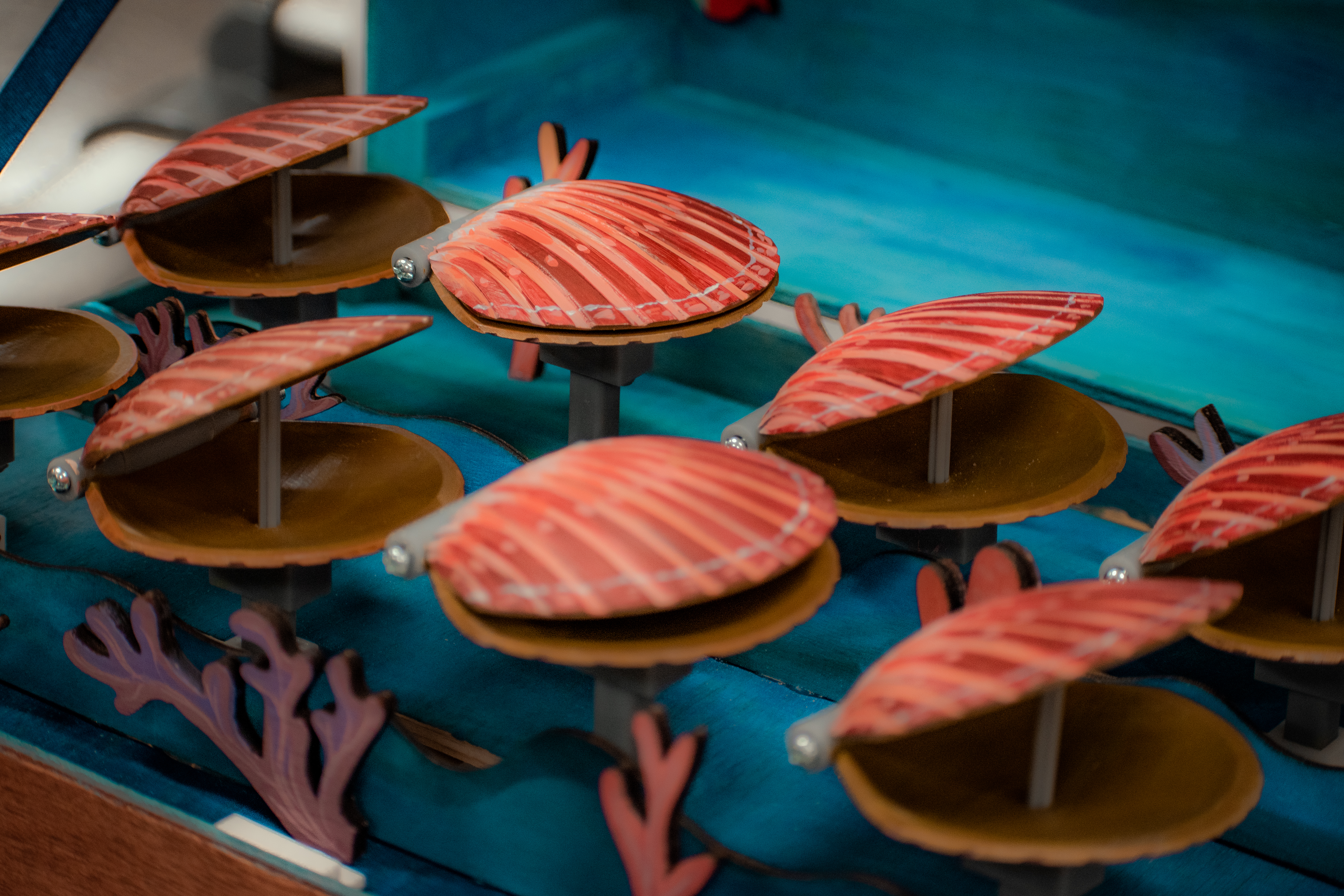
Final Photos

Distribution of Work
This project was a group project. Team members include Christine Zhou (me), Zoe Lee, Vivian Li, Shaun Latip, and Eliza Noxon.
Christine did hardware/mechanism design, electrical, painting, and debugging.
Zoe did woodworking, painting and debugging.
Vivian did software and debugging.
Shaun did software, electrical, and debugging.
Eliza did painting, decoration, and messaging.